Nissan Sentra B18 (2020-2025) Service Manual: U1600 Front Left Door Speaker Out
Dtc Description
DTC Description
DTC DETECTION LOGIC
|
DTC No. |
CONSULT screen terms (Trouble diagnosis content) |
DTC detection condition |
||
|---|---|---|---|---|
|
U1600–13 |
Front left door speaker out (Front door speaker LH) |
OPEN |
Diagnosis condition |
When ignition switch is ON. |
|
Signal (terminal) |
|
|||
|
Threshold |
– |
|||
|
Diagnosis delay time |
30 seconds or more |
|||
|
U1600–1A |
SHORT |
Diagnosis condition |
When ignition switch is ON. |
|
|
Signal (terminal) |
|
|||
|
Threshold |
– |
|||
|
Diagnosis delay time |
30 seconds or more |
|||
|
U1600–11 |
GND-SHORT |
Diagnosis condition |
When ignition switch is ON. |
|
|
Signal (terminal) |
|
|||
|
Threshold |
– |
|||
|
Diagnosis delay time |
30 seconds or more |
|||
|
U1600–12 |
VB-SHOR |
Diagnosis condition |
When ignition switch is ON. |
|
|
Signal (terminal) |
|
|||
|
Threshold |
– |
|||
|
Diagnosis delay time |
30 seconds or more |
|||
POSSIBLE CAUSE
-
FR DR SP LH+ open, short, short to ground, short to voltage
-
FR DR SP LH− open, short, short to ground, short to voltage
-
Front door speaker LH
-
Bose speaker amp.
FAIL-SAFE
—
Confirmation Procedure
Confirmation Procedure
-
PERFORM DTC CONFIRMATION PROCEDURE
-
 CONSULT
-
Ignition switch ON.
-
Ignition switch OFF and wait at least 30 seconds.
-
Ignition switch ON and wait at least 30 seconds or more.
-
Select “Self Diagnostic Result� mode of “AUDIO AMP.�.
-
Check DTC.
-
Is DTC U1600 detected?
YES>>Refer to DTC Diagnosis Procedure.
NO>>To check malfunction symptom before repair: Refer to Intermittent Incident.
NO>>Confirmation after repair: Inspection End
-
Dtc Diagnosis Procedure
DTC Diagnosis Procedure
-
DETERMINE MALFUNCTION TYPE
-
CONSULT
-
Ignition switch ON.
-
Ignition switch OFF and wait at least 30 seconds.
-
Ignition switch ON and wait at least 30 seconds or more.
-
Select “Self Diagnostic Result� mode of “AUDIO AMP.�.
-
Check DTC.
-
Is DTC U1600–11, 12, 13 or 1C detected?
YES >>13 [OPEN], or 11 [GND–SHORT] – GO TO 2.
YES >>1C [SHORT] – GO TO 3.
YES >>12 [VB–SHOR] – GO TO 4.
NO >>Refer to Intermittent Incident.
-
-
CHECK SOUND SIGNAL CIRCUITS FOR OPEN OR SHORT TO GROUND
-
-
Ignition switch OFF.
-
Disconnect Bose speaker amp. connector and front door speaker LH connector.
-
Check the continuity between Bose speaker amp. connector and front door speaker LH connector.
Bose speaker amp.
Front door speaker LH
Continuity
Connector
Terminal
Connector
Terminal
B96
2
D13
1
Yes
6
2
-
Check the continuity between Bose speaker amp. connector and ground.
Bose speaker amp.
—
Continuity
Connector
Terminal
B96
2
Ground
No
6
-
Is the inspection result normal?
YES >>GO TO 5.
NO >>Repair or replace harness or connectors.
-
-
CHECK SOUND SIGNAL CIRCUITS FOR SHORT
-
-
Ignition switch OFF.
-
Disconnect Bose speaker amp. connector and front door speaker LH connector.
-
Check the continuity between the terminals of Bose speaker amp. connector.
Bose speaker amp.
Continuity
Connector
Terminals
B96
2
6
No
-
Is the inspection result normal?
YES >>GO TO 5.
NO >>Repair or replace harness or connectors.
-
-
CHECK SOUND SIGNAL CIRCUIT FOR SHORT TO POWER SUPPLY
-
-
Ignition switch OFF.
-
Disconnect Bose speaker amp. connector and front door speaker LH connector.
-
Ignition switch ON.
-
Check the voltage between Bose speaker amp. connector and ground.
Bose speaker amp.
(—)
Voltage
(Approx.)
(+)
Connector
Terminal
B96
2
Ground
0 V
6
-
Is the inspection result normal?
YES >>GO TO 5.
NO >>Repair or replace harness or connectors.
-
-
CHECK FRONT DOOR SPEAKER LH SIGNAL
-
-
Connect Bose speaker amp. connector and front door speaker LH connector.
-
Ignition switch ON.
-
AV control unit ON.
-
Check signal between the terminals of Bose speaker amp. connector.
Bose speaker amp.
Condition
Reference value
Connector
(+)
(−)
Terminals
B96
2
6
Audio signal output
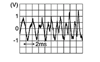
-
Is the inspection result normal?
YES >>Replace front door speaker LH. Refer to Removal and Installation.
NO >>Replace Bose speaker amp. Refer to Removal and Installation.
-
Other materials:
Seat. Preparation
Preparation
Special Service Tool
Special Service Tool
The actual shape of the tools may differ from those
illustrated here.
Tool number
(TechMate No.)
Tool name
...
Brake System. Precaution. Precautions
Precautions
Precaution for Supplemental Restraint System (srs) "air Bag" and "seat Belt Pre-Tensioner"
Precaution for Supplemental Restraint System (SRS) "AIR BAG" and "SEAT BELT PRE-TENSIONER"
The Supplemental Restraint System such as
“AIR BAG� and “SEAT BELT PRE-T ...
B20c7-15 A/c Clutch
Dtc Description
DTC Description
DTC DETECTION LOGIC
DTC No.
CONSULT screen terms
(Trouble diagnosis content)
DTC detection condition
...