Nissan Sentra Service Manual: Component parts
Component parts location
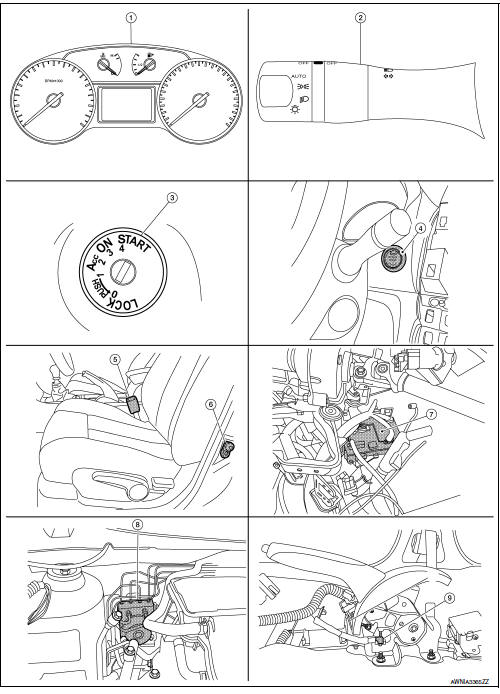
- Combination meter
- Combination switch (lighting and turn signal switch)
- Key switch (without intelligent key system)
- Push-button ignition switch (with intelligent key system)
- Seat belt buckle switch lh
- Front door switch lh
- Bcm (view with instrument panel removed)
- ABS actuator and electric unit (control unit)
- Parking brake switch (view with center console removed)
Component description
| Unit | Description |
| Combination meter |
|
| Lighting switch | Transmits lighting switch status signal to the bcm. |
| BCM | Transmits signals provided by various units to the combination meter with can communication line. |
| Front door switch lh | Transmits door switch signal to bcm. |
| Key switch | Transmits key switch signal to bcm. |
| Push-button ignition switch | Provides ignition switch status to the bcm |
| Seat belt buckle switch LH | Transmits seat belt buckle switch lh signal to the combination meter. |
| Parking brake switch | Transmits parking brake switch signal to the combination meter. |
| Abs actuator and electric unit (control unit) | Transmits the vehicle speed signal to combination meter with can communication line. |

 System
Warning chime system
Warning chime system : system diagram
Warning chime system : system description
Description
The buzzer for warning chime system is installed in the combination
meter.
...
Other materials:
Starter motor drive control
STARTER MOTOR DRIVE CONTROL : System Description
SYSTEN DIAGRAM
*1: CVT models
*2: M/T models
INPUT/OUTPUT SIGNAL CHART
Sensor
Input signal to ECM
ECM function
Actuator
Crankshaft position sensor (POS)
Engine speed
Piston position
Starter ...
Consult function
FUNCTION
Diagnostic test mode
Function
Self Diagnostic Results
Self-diagnostic results such as 1st trip DTC, DTCs and 1st trip
freeze frame data or freeze frame data
can be read and erased quickly.*
Data Monitor
Input/Output data in the ECM can be read.
...
Precaution for work
When removing or disassembling each component, be careful not to damage
or deform it. If a component
may be subject to interference, be sure to protect it with a shop cloth.
When removing (disengaging) components with a screwdriver or similar
tool, be sure to wrap the component
with a ...
