Nissan Sentra B18 (2020-2025) Service Manual: System Description
Component Parts
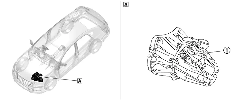
Component Parts Location
Component Parts Location
|
A. |
Transaxle assembly |
|
No. |
Component |
Function |
|---|---|---|
|
1. |
Position switch |
|
Structure and Operation
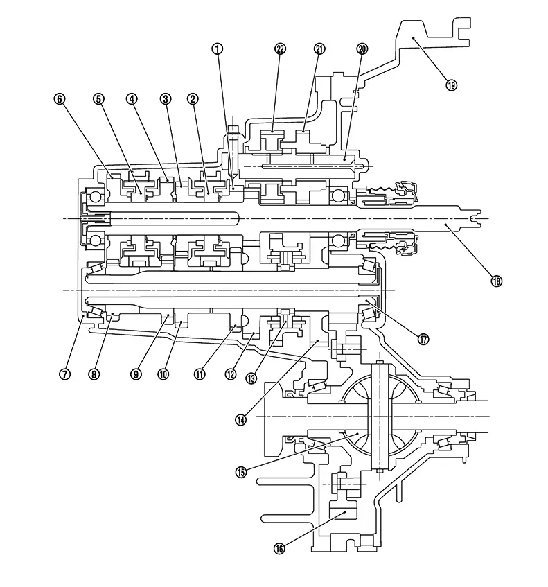
Sectional View
Sectional View
|
1. |
3rd input gear |
2. |
3rd-4th synchronizer hub assembly |
3. |
4th input gear |
|
4. |
5th input gear |
5. |
5th-6th synchronizer hub assembly |
6. |
6th input gear |
|
7. |
Transaxle case |
8. |
6th main gear |
9. |
5th main gear |
|
10. |
4th main gear |
11. |
3rd main gear |
12. |
2nd main gear |
|
13. |
1st-2nd synchronizer hub assembly |
14. |
1st main gear |
15. |
Differential |
|
16. |
Final gear |
17. |
Mainshaft |
18. |
Input shaft |
|
19. |
Clutch housing |
20. |
Reverse idler shaft |
21. |
Reverse input gear |
|
22. |
Reverse output gear |
||||
System Description
System Description
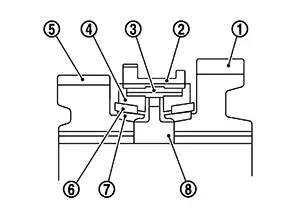
TRIPLE-CONE SYNCHRONIZER
Triple-cone synchronizers are adopted for the 1st and the 2nd gears to reduce operating force of the shifter lever.
|
1. |
: 1st main gear |
|
2. |
: 1st-2nd coupling sleeve |
|
3. |
: Insert key |
|
4. |
: Outer baulk ring |
|
5. |
: 2nd main gear |
|
6. |
: Synchronizer cone |
|
7. |
: Inner baulk ring |
|
8. |
: 1st-2nd synchronizer hub |
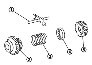
REVERSE GEAR NOISE PREVENTION FUNCTION (SYNCHRONIZING METHOD)
Reverse gear assembly consists of reverse input gear, return spring, reverse baulk ring, and reverse output gear. When the shifter lever is moved to the reverse position, the construction allows smooth shift operation by stopping the reverse idler shaft rotation by frictional force of synchronizer.
|
1. |
: Reverse fork rod |
|
2. |
: Reverse output gear |
|
3. |
: Return spring |
|
4. |
: Reverse baulk ring |
|
5. |
: Reverse input gear |
Other materials:
C1714-7b Low Tire Pressure Rr
Dtc Description
DTC Description
Note:
The Signal Tech II Tool [– (NI-50190)] can be used
to perform the following functions: Refer to the Signal Tech II User
Guide for additional information.
Activate and display TPMS sensor IDs
Display tire pressure rep ...
Refrigerant
Description
Description
CONNECTION OF SERVICE TOOLS AND
EQUIPMENT
1.
Shut-off valve
2.
A/C service valve
...
Intelligent Key Button Operation Has Poor Range (all Keys)
Description
Description
Intelligent Key button operation has poor
range.
SYMPTOM TABLE (BOTH INTELLIGENT KEYS HAVE
THE SAME SYMPTOMS)
Door lock operation (remote
keyless entry)
...