Nissan Sentra Service Manual: System description
Component parts
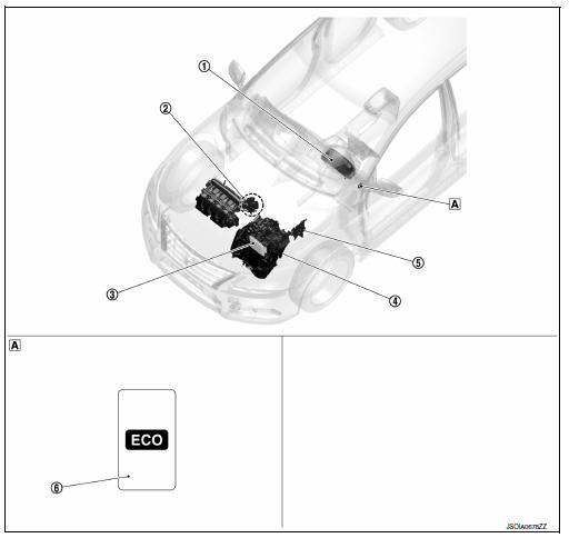
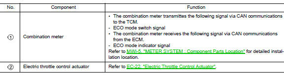
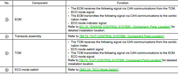
Component parts location
 Instrument lower finisher
Component description
Eco mode switch
- The ECO mode switch is installed to the instrument lower finisher.
- When the eco mode indicator lamp on the combination meter is off and the eco mode switch is pressed, the eco mode is active and the eco mode indicator lamp is on.
- When the ECO mode indicator lamp on the combination meter is ON and the ECO mode switch is pressed, the ECO mode is cancelled and the ECO mode indicator lamp is OFF.
Eco mode indicator lamp
Design/purpose
The eco mode indicator lamp inform the driver that the vehicle is in eco mode.
Bulb check
Not applicable
Signal path
- TCM receives ECO mode switch signal (ON/OFF) from combination meter via CAN communication. Based on the signal, TCM transmits ECO mode signal to ECM via CAN communication.
- ECM transmits ECO mode indicator signal to combination meter via CAN communication. Based on the signal, combination meter illuminates ECO mode indicator lamp.
Lighting condition
When all of the following conditions are satisfied.
- Ignition switch: on
- The eco mode switch is pressed when the eco mode indicator lamp is off
Shutoff condition
When any of the condition listed below is satisfied.
- Ignition switch: other than on
- The eco mode switch is pressed when the eco mode indicator lamp is on.
- The SPORT mode switch is pressed when the ECO mode indicator lamp is ON.
System
Eco mode control
Eco mode control : system description
System diagram
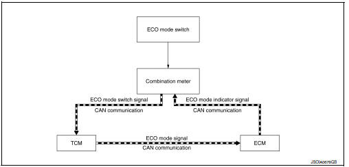
System discription
- Tcm receive eco mode switch signal (on/off) from combination meter via can communication. Tcm transmit eco mode signal to ecm via can communication according to the signal.
- ECM transmit ECO mode indicator signal to combination meter via CAN communication. Combination meter illuminates ECO mode indicator lamp according to the signal.
Each ecu control
- For tcm control, refer to tm-104, "eco mode control : system description".
- For ECM control, refer to EC-52, "ECO MODE CONTROL : System Description".
 Precaution
Precaution for supplemental restraint system (srs) "air bag" and "seat
belt pre-tensioner"
The supplemental restraint system such as “air bag” and “seat belt pre- ...
 Ecu diagnosis information
Eco mode
List of ecu reference
...
Other materials:
ABS Warning lamp
Component Function Check
1.CHECK ABS WARNING LAMP FUNCTION
Check that ABS warning lamp in combination meter turns ON for
approximately 2 seconds after ignition switch
is turned ON.
Is the inspection result normal?
YES >> Inspection End.
NO >> Proceed to diagnosis procedure. ...
Abs branch line circuit
Diagnosis procedure
1.Check connector
Turn the ignition switch off.
Disconnect the battery cable from the negative terminal.
Check the terminals and connectors of the abs actuator and electric unit
(control unit) for damage, bend
and loose connection (unit side and connector side).
...
Trunk lid
Trunk lid assembly
Trunk lid assembly : exploded view
Trunk lid hinge LH/RH
Torsion bar LH/RH
Torsion bar clips
Trunk lid finisher (if equipped)
Emergency release handle
Emergency release handle clip
Emergency release handle cable
Trunk lid lock
Trunk lid bumpers
License lam ...
