Nissan Sentra Service Manual: System description
Component parts
Component parts location
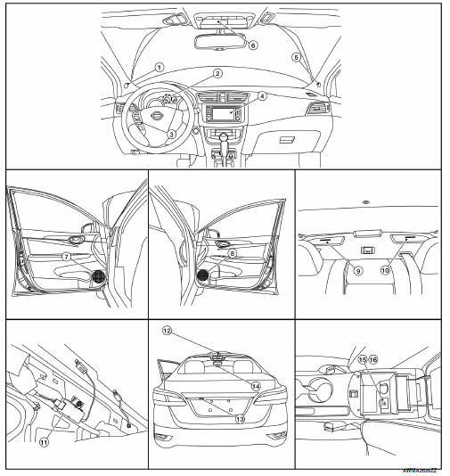
- Front tweeter lh
- GPS antenna
- Steering switches
- Av control unit
- Front tweeter rh
- Microphone
- Front door speaker LH
- Front door speaker rh
- Rear speaker RH
- Rear speaker lh
- Antenna amp.
- Satellite antenna
- Rear view camera
- Window antenna
- USB interface
- Aux jack
Component description
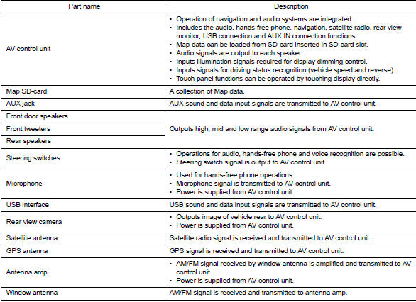
System
System diagram
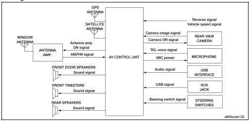
System description
Refer to owner’s manual for navigation and audio system operating instructions.
Audio function and display are built into av control unit.
This navigation has the following functions.
- Map data on sd-card.
- Full support for playback of music from ipodВ® and usb device
- High resolution color 5.8 inch display with touch panel function
- Fm/am twin digital tuner
- Usb mass storage connection
- Satellite radio
- Hands-free phone system
iPodВ® is a trademark of Apple inc., registered in the U.S. and other countries.
Navigation system function
Description
- The navigation system can be operated by control panel of the av control unit and display (touch panel) of the av control unit
- Guide sound during the operation of the navigation system is output from av control unit to front speakers.
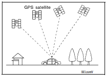
- AV control unit calculates the vehicle location based on the signals from GYRO (angle speed sensor), vehicle sensor, and GPS satellite, as well as the map data from map SD-card. The vehicle location is displayed on the AV control unit.
Position detection principle
The navigation system periodically calculates the vehicle's current position according to the following three signals:
- Travel distance of the vehicle as determined by the vehicle speed sensor
- Turning angle of the vehicle as determined by the gyroscope (angular velocity sensor)
- Direction of vehicle travel as determined by the gps antenna (gps information)
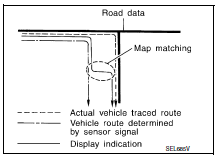
The current position of the vehicle is then identified by comparing the calculated vehicle position with map data read from the map sd-card (map-matching), and indicated on the screen as a vehicle mark. More accurate data is judged and used by comparing vehicle position detection results found by the gps with the result by map-matching.
The current vehicle position will be calculated by detecting the distance the vehicle moved from the previous calculation point and its direction.
- Travel distance
Travel distance calculations are based on the vehicle speed sensor input signal. Therefore, the calculation may become incorrect as the tires wear down. To prevent this, an automatic distance correction function has been adopted.
- Travel direction
Change in the travel direction of the vehicle is calculated by a gyroscope (angular velocity sensor) and a gps antenna (gps information).
They have both advantages and disadvantages.
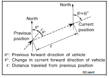
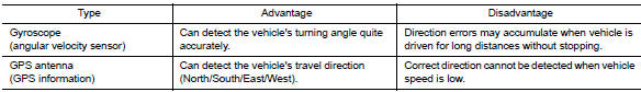
More accurate traveling direction is detected because priorities are set for the signals from these two devices according to the situation.
Map-matching
Map-matching compares a current location detected by the method in the “location detection principle” with a road map data from map sd-card.
Note:
The road map data is based on data stored in the map sd-card.
The vehicle position may not be corrected under the following circumstances and after driving for a certain time when gps information is difficult to receive. In this case, the vehicle mark on the display must be corrected manually
- In map-matching, alternative routes to reach the destination will be
shown and prioritized, after the road on which the vehicle is currently
driven has been judged and the vehicle mark has been repositioned.
Alternative routes will be shown in different order of priority, and the incorrect road can be avoided if there is an error in distance and/or direction.
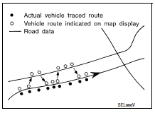
Routes are of the same priority if two roads are running in parallel.
Therefore, the vehicle mark may appear on either of them alternately, depending on maneuvering of the steering wheel and configuration of the road.
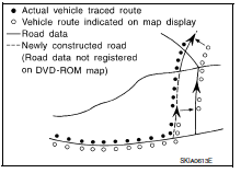
- Map-matching does not function correctly when a road on which
the vehicle is driving is new and not recorded in the map SD-card,
or when road pattern stored in the map data and the actual road
pattern are different due to repair.
The map-matching function may find another road and position the vehicle mark on it when driving on a road not present in the map.
Then, the vehicle mark may change to it when the correct road is detected.
- Effective range for comparing the vehicle position and travel direction calculated by the distance and direction with the road data read from the map sd-card is limited. Therefore, correction by map-matching is not possible when there is an excessive gap between current vehicle position and the position on the map.
Gps (global positioning system)
Gps (global positioning system) is developed for and is controlled by the us department of defense. The system utilizes gps satellites (navstar), transmitting out radio waves while flying on an orbit around the earth at an altitude of approximately 21,000 km (13,049 mile).
The receiver calculates the travel position in three dimensions (latitude/ longitude/altitude) according to the time lag of the radio waves that four or more gps satellites transmit (three-dimensional positioning).
The gps receiver calculates the travel position in two dimensions (latitude/longitude) with the previous altitude data if the gps receiver receives only three radio waves (two-dimensional positioning).
Gps position correction is not performed while stopping the vehicle.
Accuracy of the gps will deteriorate under the following conditions:
- In two-dimensional positioning, gps accuracy will deteriorate when altitude of the vehicle position changes.
- The position of GPS satellite affects GPS detection precision. The position detection may not be precisely performed.
- The position detection is not performed if gps receiver does not receive
radio waves from gps satellites.
(Inside a tunnel, parking in a building, under an elevated highway etc.) Gps receiver may not receive radio waves from gps satellites if any object is placed on the gps antenna.
Note:
- The detection result has an error of approximately 10 m (32.81 ft) even with a high-precision three dimensional positioning
- There may be cases when the accuracy is lowered and radio waves are stopped intentionally because the gps satellite signal is controlled by the us trace control center.
Satellite radio function
- Satellite radio function is built into AV control unit.
- Sound signal (satellite radio) is received by satellite antenna and transmitted to av control unit. Av control unit outputs sound signal to each speaker.
Auxiliary input function
- Sound can be output from an external device by connecting a device with USB connector and AUX jack.
- AUX sound signals are transmitted to each speaker via AV control unit.
Rear view monitor function
Camera image operation principle
- The av control unit supplies power to the rear view camera when receiving a reverse signal.
- The rear view camera transmits camera images to the av control unit when power is supplied from the av control unit.
- The av control unit combines a warning message and fixed guide lines with an image received from the rear view camera to display a rear view camera image on the screen.
Usb connection function
- IpodВ® or music files in usb memory can be played.
- Sound signals are transmitted from usb connector and aux jack to the av control unit and output to each speaker and tweeter.
- iPodВ® is recharged when connected to USB connector and AUX jack.
Note:
Use the enclosed usb harness when connecting ipodВ® to usb connector and aux jack.
IpodВ® is a trademark of apple inc., Registered in the u.S. And other countries.
Speed sensitive volume system
- Volume level of this system goes up and down automatically in proportion to the vehicle speed.
- The control level can be selected by the customer.
Hands-free phone system
- BluetoothВ® control is built into av control unit.
- The connection between cellular phone and av control unit is performed with bluetoothВ® communication.
- The voice guidance signal is input from the av control unit and output to the front speakers when operating the cellular phone.
When a call is originated
- Spoken voice sound output from the microphone (microphone signal) is input to av control unit.
- Av control unit outputs to cellular phone with bluetoothВ® communication as a tel voice signal.
- Voice sound is then heard at the other party.
When receiving a call
- Voice sound is input to own cellular phone from the other party.
- Tel voice signal is input to av control unit by establishing bluetoothВ® communication from cellular phone, and the signal is output to front speakers.
Diagnosis system (av control unit)
Description
The av control unit on board diagnosis performs the functions listed in the table below:
Perform consult diagnosis if the av control unit on board diagnosis does not start or the screen does not display anything.
On Board Diagnosis Function
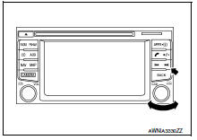
Method of starting
- Turn the ignition on.
- Turn the audio system off.
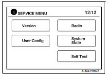
- While pressing the forward seek button, turn the tune-dial counterclockwise 3 or more clicks, then clockwise 3 or more clicks, then counterclockwise 3 or more clicks. Shifting from current screen to previous screen is performed by pressing back button.
- The trouble diagnosis initial screen is displayed, and version, user config, radio, system state or self test can be selected.
CONSULT Function
Consult functions
Consult performs the following functions via communication with the av control unit.
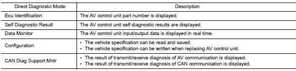
Ecu identification
The part number of av control unit is displayed.
Self diagnostic result
Refer to AV-233, "DTC Index".
DATA MONITOR
CONFIGURATION
Refer to AV-251, "CONFIGURATION (AV CONTROL UNIT) : Description".
CAN DIAG SUPPORT MNTR
Refer to LAN-13, "CAN Diagnostic Support Monitor".
 Preparation
Special Service Tools
The actual shape of the tools may differ from those illustrated here.
Commercial Service Tools
...
 Ecu diagnosis information
Av control unit
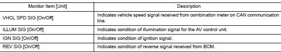
Reference value
TERMINAL LAYOUT
PHYSICAL VALUES
Dtc index
...
Other materials:
Precaution
Precaution for Supplemental Restraint System (SRS) "AIR BAG" and "SEAT
BELT PRE-TENSIONER"
The Supplemental Restraint System such as “AIR BAG” and “SEAT BELT PRE-TENSIONER”,
used along
with a front seat belt, helps to reduce the risk or severity of injur ...
Rear shock absorber
Exploded View
Rear suspension beam
Shock absorber
Bound bumper
Bound bumper cover
Washer
Bushing
Distance tube
Bushing
Washer
Piston rod lock nut
Cap
Front
Removal and Installation
REMOVAL
Remove the rear shock tower access flap.
Remove the cap from the rear s ...
Service data and specifications (SDS)
Steering Wheel
Steering Angle
Steering Column
STEERING COLUMN LENGTH
TILT MECHANISM OPERATING RANGE
Power Steering Gear
STEERING OUTER SOCKET AND INNER SOCKET
RACK STROKE
...
