Nissan Sentra Service Manual: System description
Component parts
Component part location
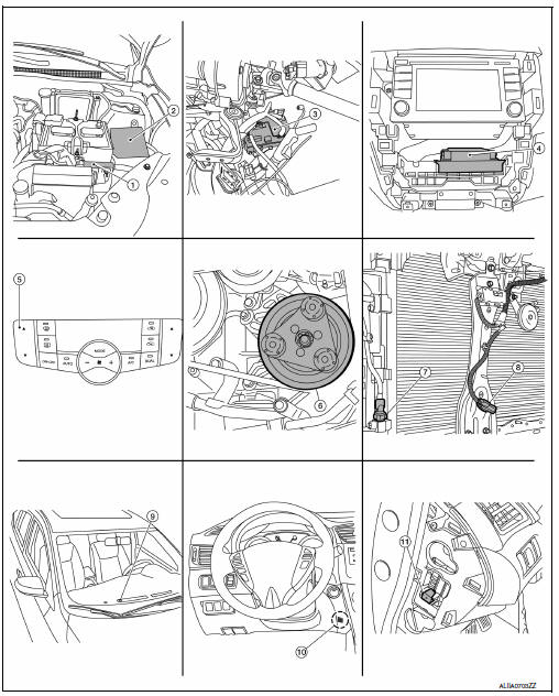
- ECM
- IPDM E/R
- BCM (view with instrument panel removed)
- A/C auto amp. (view with A/C switch assembly removed)
- A/C switch assembly
- A/C Compressor
- Refrigerant pressure sensor (view with front bumper fascia removed)
- Ambient sensor
- Sunload sensor
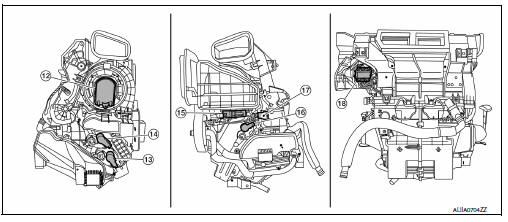
- In-vehicle sensor
- Blower motor relay
- Blower motor (view with front A/C assembly removed from vehicle)
- Air mix door motor RH
- Mode door motor
- Intake door motor
- Air mix door motor LH
- Intake sensor
- Variable blower control
Component description
| Component | Description |
| A/C auto amp. | A/C auto amp. controls front automatic air conditioning system by inputting and calculating signals from each sensor and each switch. |
| A/C Compressor | Vaporized refrigerant is drawn into the A/C compressor from the evaporator, where it is compressed to a high pressure, high temperature vapor. The hot, compressed vapor is then discharged to the condenser. |
| A/C switch assembly | The A/C switch assembly controls the operation of the A/C and heating system based on inputs from the temperature control knob, the mode switches, the blower control dial, the ambient temperature sensor, the intake sensor, and inputs received from the ECM across the CAN. Diagnosis of the A/C switch assembly can be performed using the CONSULT. |
| Air mix door motor LH | The air mix door controls the mix of hot or cold air that enters the ventilation system. It is controlled by the A/C auto amp. based on the position of the temperature dial. The air mix door motor LH receives position commands from the A/C auto amp. |
| Air mix door motor RH | The air mix door controls the mix of hot or cold air that enters the ventilation system. It is controlled by the A/C auto amp. based on the position of the temperature dial. The air mix door motor RH receives position commands from the A/C auto amp. |
| Ambient sensor | The ambient sensor measures the temperature of the air surrounding the vehicle. The sensor uses a thermistor which is sensitive to the change in temperature. The electrical resistance of the thermistor decreases as temperature increases. |
| BCM | The BCM receives the fan ON and A/C ON signals from the A/C auto amp. and sends a compressor ON request to the ECM. |
| Blower motor | The blower motor varies the speed at which the air flows through the ventilation system. |
| Blower motor relay | The blower motor relay controls the flow of current to fuse 20, 21 and 22 in the Fuse Block (J/B). The relay is connected directly to ground, and is energized when the ignition switch is in the ON or START position. |
| ECM | The ECM sends a compressor ON request to the IPDM E/R based on the status of engine operation and load as well as refrigerant pressure information. If all the conditions are met for A/C operation, the ECM transmits the compressor ON request to the IPDM E/R. The ECM shares the refrigerant pressure sensor signal, engine RPM, and engine coolant temperature with the A/C auto amp. via CAN communication line |
| Fuse Block (J/B) | Located in the passenger compartment, behind the left lower IP, the Fuse Block (J/B) contains the blower motor relay and several fuses required for the air conditioner control system. |
| Intake door motor | The intake door motor controls the position of the intake door.
Fresh air is allowed to enter the cabin
in one position, and recirculated inside air is allowed to enter in the
other position. At times the A/C
auto amp. may command partial fresh or recirculation based on evaporator
or coolant temperatures.
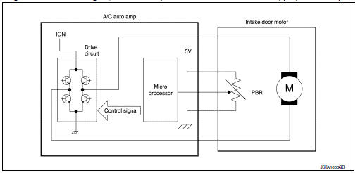
The intake door motor receives position commands from the A/C auto amp. and reports actual door position back via an LCU (Local Control Unit) installed inside the motor. The LCU reads the door position from a Position Balanced Resistor (PBR), also part of the motor, and returns that information to the A/C auto amp. The LCU switches the polarity of the circuits connected to the DC motor to drive the motor forward or backward as requested by the A/C auto amp. |
| Intake sensor | The intake sensor measures the temperature of the front evaporator fins. The sensor uses a thermistor which is sensitive to the change in temperature. The electrical resistance of the thermistor decreases as temperature increases. |
| In-vehicle sensor | In-vehicle sensor measures temperature of intake air that flows
through aspirator to passenger room.
The sensor uses a thermistor which is sensitive to the change in temperature. The electrical resistance of the thermistor decreases as temperature increases. |
| IPDM E/R | Refer to PCS-7, "RELAY CONTROL SYSTEM : System Description". |
| Mode door motor | The mode door controls the direction the conditioned air passes
through the ventilation system.
Through a series of levers and gears, the mode door controls the defrost door, the foot door, and the vent door. There are 5 preset positions: VENT, B/L, FOOT, D/F, and DEF. The FOOT position can be set to allow some airflow through to the defroster vent, or to completely block the defroster vent using the CONSULT. The mode door motor receives position commands from the A/C auto amp. |
| Refrigerant pressure sensor | Refer to EC-29, "Refrigerant Pressure Sensor". |
| Sunload sensor | Sunload sensor measures sunload amount. This sensor is a dual system so that sunload for driver side and passenger side are measured separately. This sensor converts sunload amount to voltage signal by photodiode and transmits to A/C auto amp. |
System
System diagram
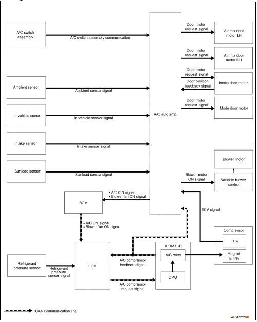
System description
- Automatic air conditioning system is controlled by each function of A/C auto amp., ECM, IPDM E/R and BCM.
Control by A/C auto amp.
- HAC-13, "Air Flow Control"
- HAC-14, "Air Inlet Control"
- HAC-15, "Air Outlet Control"
- HAC-15, "Compressor Control"
- HAC-15, "Door Control"
- HAC-20, "Temperature Control"
- Correction for input value of each sensor
Ambient sensor (setting temperature correction)
- A/C auto amp. controls passenger room temperature so that the optimum level always matches the temperature level that the passenger may feel. Correction is applied to the target temperature that is set using temperature control dial, according to ambient temperature detected by ambient sensor.
In-vehicle sensor [in-vehicle temperature correction]
- Passenger room temperature detected by in-vehicle sensor is corrected for each front air conditioning control (driver side and passenger side).
Intake sensor (intake temperature correction)
- A/C auto amp. performs correction to change recognition intake temperature of A/C auto amp. quickly when difference is large between recognition intake temperature and intake temperature detected by intake temperature sensor. The correction is performed to change recognition intake temperature slowly when difference is small.
Sunload sensor (sunload amount correction)
- Sunload amount detected by sunload sensor is corrected for each air conditioning control.
- A/C auto amp. performs correction to change recognition sunload amount of A/C auto amp. slowly when sunload amount changes quickly, for example when entering or exiting a tunnel.
Set temperature correction
A/C auto amp. performs correction to the target temperature set by the temperature control switch so as to match the temperature felt by the passengers depending on the ambient temperature detected by the ambient sensor, and controls it so the in-vehicle temperature is always the most suitable.
Control by ECM
- Cooling fan control
Refer to EC-47, "COOLING FAN CONTROL : System Description".
- Air conditioning cut control
Refer to EC-46, "AIR CONDITIONING CUT CONTROL : System Description".
Control by IPDM E/R
- Relay control
Refer to PCS-7, "RELAY CONTROL SYSTEM : System Description".
- Cooling fan control
Refer to EC-47, "COOLING FAN CONTROL : System Description".
Control by BCM
- Relay control
Refer to BCS-8, "BODY CONTROL SYSTEM : System Description".
Air flow control
DESCRIPTION
- A/C auto amp. changes duty ratio of blower motor drive signal and controls air flow continuously. When air flow is increased, duty ratio of blower motor control signal gradually increases to prevent a sudden increase in air flow.
- In addition to manual control and automatic control, air flow control consists of starting fan speed control, low coolant temperature starting control, high in-vehicle temperature starting control and fan speed control at door motor operation
AUTOMATIC AIR FLOW CONTROL
- A/C auto amp. decides target air flow depending on target air mix door opening angle.
- A/C auto amp. changes duty ratio of blower motor control signal and controls the air flow continuously so that air flow matches the target air flow.
- When air outlet is VENT or B/L, the minimum air flow is changed depending on sunload.
STARTING AIR FLOW CONTROL
- When blower motor is activated, A/C auto amp. gradually increases duty ratio of blower motor control signal to prevent a sudden increase in discharge air flow.
- It takes approximately 8 seconds for air flow to reach HI from LOW.
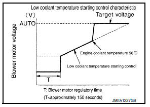
LOW COOLANT TEMPERATURE STARTING CONTROL
If the engine coolant temperature is 56В°C (133В°F) or less, to prevent a cold discharged air flow, A/C auto amp. suspends blower motor activation for a maximum of 150 seconds depending on target air mix door opening angle. After this, blower motor control signal is increased gradually, and blower motor is activated.
HIGH IN-VEHICLE TEMPERATURE STARTING CONTROL
When front evaporator fin temperature is high [intake sensor value is 35В°C (95В°F) or more], to prevent a hot discharged air flow, A/C auto amp. suspends blower motor activation for approximately 3 seconds so that front evaporator is cooled by refrigerant.
FAN SPEED CONTROL AT DOOR MOTOR OPERATION
When mode door motor is activated while air flow is more than the specified value, A/C auto amp. reduces fan speed temporarily so that mode door moves smoothly.
Air inlet control
The intake door is automatically controlled by the temperature setting, ambient temperature, in-vehicle temperature, intake temperature, amount of sunload and ON/OFF operation of the compressor.
Intake door automatic control selects FRE, 20% FRE, or REC depending on a target air mix door opening angle, based on in-vehicle temperature, ambient temperature, and sunload.
Air outlet control
- While air outlet is in automatic control, A/C auto amp. selects the mode door position depending on a target air mix door angle and outlet air temperature calculated from sunload.
- If ambient temperature is excessively low, D/F is selected to prevent windshield fogging when air outlet is set to FOOT.
Compressor control
DESCRIPTION
- When the compressor activation condition is satisfied while blower motor is activated, A/C auto amp. transmits A/C ON signal and blower fan ON signal to BCM.
- BCM transmits the A/C ON signal and blower fan ON signal to the ECM via CAN communication line.
- ECM judges that the compressor can be activated depending on the state of each sensor (refrigerant pressure sensor signal and others) and transmits A/C compressor request signal to IPDM E/R via CAN communication.
- IPDM E/R turns A/C relay ON and activates the compressor depending on request from ECM.
COMPRESSOR PROTECTION CONTROL AT PRESSURE MALFUNCTION
When high-pressure side value that is detected by refrigerant pressure sensor is as per the following state, ECM requests IPDM E/R to turn A/C relay OFF and stops the compressor.
- 3.12 MPa (31.82 kg/cm2, 452.4 psi) or more (When the engine speed is less than 1,500 rpm)
- 2.74 MPa (27.95 kg/cm2, 397.3 psi) or more (When the engine speed is 1,500 rpm or more)
- 0.14 MPa (1.43 kg/cm2, 20.3 psi) or less
COMPRESSOR OIL CIRCULATION CONTROL
When the engine starts while the engine coolant temperature is 56В°C (133В°F) or less, ECM activates the compressor for approximately 6 seconds and circulates the compressor lubricant once.
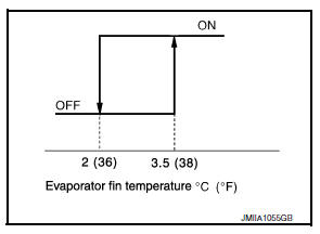
LOW TEMPERATURE PROTECTION CONTROL
- When intake sensor detects that front evaporator fin temperature is 2В°C (36В°F) or less, A/C auto amp. requests ECM to turn compressor OFF, and stops the compressor.
- When the front evaporator fin temperature returns to 3.5В°C (38В°F) or more, the compressor is activated.
AIR CONDITIONING CUT CONTROL
When set engine is running is excessively high load condition, ECM requests IPDM E/R to turn A/C relay OFF, and stops the compressor. Refer to EC-46, "AIR CONDITIONING CUT CONTROL : System Description".
Door control
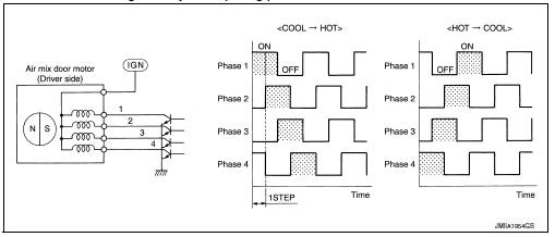
AIR MIX DOOR MOTOR (DRIVER SIDE)
DESCRIPTION
- The step motor system is adopted for air mix door motor (driver side).
- When a drive signal is input from A/C auto amp. to door motor, a step motor built into the door motor rotates according to the drive signal, and then stops at the target door position.
- Rotation of motor is transmitted to air mix door (driver side) [upper air mix door (driver side) and lower air mix door (driver side)] by link, rod and lever, then air flow temperature (driver side) is switched.
DRIVE METHOD
- The 4 drive coils are excited in sequence in order to drive the motor.
- Direction of rotation is changeable by recomposing pattern of excitation.
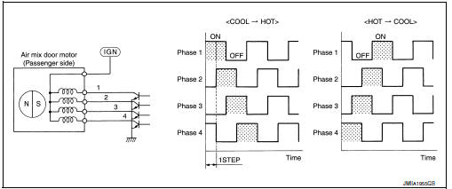
AIR MIX DOOR MOTOR (PASSENGER SIDE)
DESCRIPTION
- The step motor system is adopted for air mix door motor (passenger side).
- When a drive signal is input from A/C auto amp. to door motor, a step motor built into the door motor rotates according to the drive signal, and then stops at the target door position.
- Rotation of motor is transmitted to air mix door (passenger side) [upper air mix door (passenger side) and lower air mix door (passenger side)] by link, rod and lever, then air flow temperature (passenger side) is switched.
DRIVE METHOD
- The 4 drive coils are excited in sequence in order to drive the motor.
- Direction of rotation is changeable by recomposing pattern of excitation.
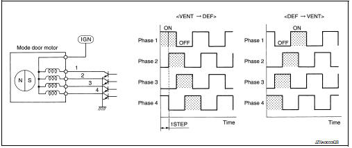
MODE DOOR MOTOR
DESCRIPTION
- The step motor system is adopted for mode door motor.
- When a drive signal is input from A/C auto amp. to door motor, a step motor built into the door motor rotates according to the drive signal, and then stops at the target door position
- Rotation of motor is transmitted to mode door (center ventilator and defroster door, sub defroster door, side ventilator door, and foot door) by link, rod, and lever, then air outlet is switched.
Drive method
- The 4 drive coils are excited in sequence in order to drive the motor.
- Direction of rotation is changeable by recomposing pattern of excitation.
Intake door motor
- Intake door motor consists of motor that drives door and PBR (Potentio Balance Register) that detects door position.
- Motor operates intake door according to control signal from A/C auto amp.
- Rotation of motor is transmitted to intake door by lever, then air inlet is switched.
- PBR (Potentio Balance Register) transmits PBR feedback signal to A/C auto amp. according to motor position.
- According to PBR feedback signal, A/C auto amp. monitors that motor is in an appropriate door position.
Switches and their control function
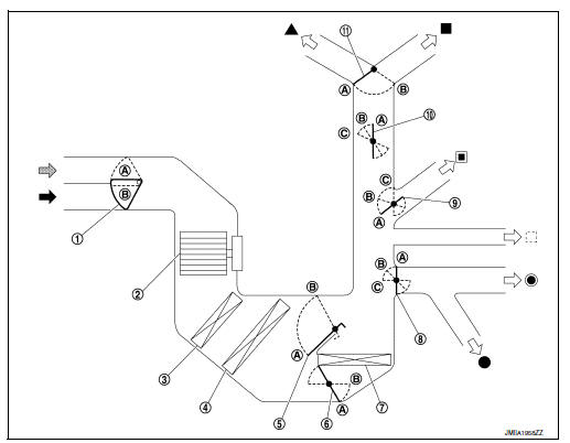
- Intake door
- Blower motor
- Air conditioner filter
- Evaporator
- Upper air mix door (driver side/passenger side)
- Lower air mix door (driver side/passenger side)
- Heater core
- Foot door
- Side ventilator door
- Sub defroster door
- Center ventilator and defroster door
 Fresh air intake
 Recirculation air
 Discharge air
 Defroster
 Center ventilator
 Side ventilator
 Rear ventilator
 Front foot
 Rear foot
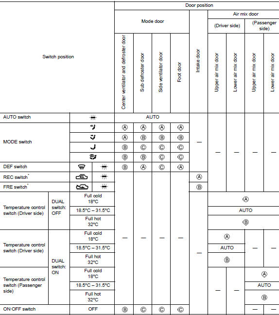
*: Inlet status is displayed by indicator during activating automatic control
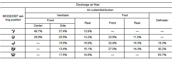
Air distribution
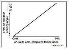
Temperature control
- When ignition switch is in the ON position, A/C auto amp. always automatically controls temperature regardless of front air conditioning operational state.
- A/C auto amp. calculates the target air mix door opening angle depending on set temperature, in-vehicle temperature, ambient temperature, and sunload
- Air mix door is controlled depending on the comparison of current air mix door opening angle and target air mix door opening angle.
- Regardless of in-vehicle temperature, ambient temperature, and sunload, air mix door is fixed at the fully cold position when set temperature is 18.0В°C (60В°F), and at the fully hot position when set temperature is 32.0В°C (90В°F).
Fail-safe
FAIL-SAFE FUNCTION
If a communication error exists between the A/C auto amp., and the AV control unit and preset switch for 30 seconds or longer, air conditioning is controlled under the following conditions:
A/C switch : ON
Air outlet : AUTO
Air inlet : FRE (Fresh air intake)
Blower fan speed : AUTO
Set temperature : Setting before communication error occurs
OPERATION
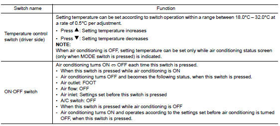
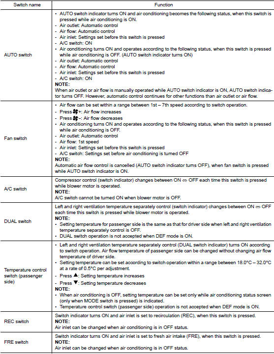
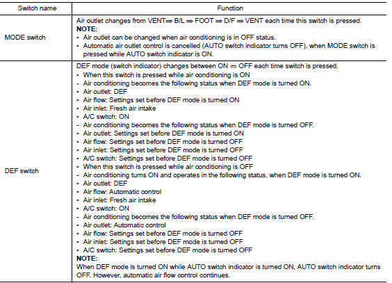
Switch Name and Function
CONTROL OPERATION
A/C Switch Assembly
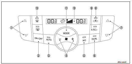
- Temperature control switch (driver side)
- ON/OFF switch
- AUTO switch
- Fan control switch
- A/C switch
- DUAL switch
- Temperature control switch (passenger side)
- Recirculation switch
- Fresh air switch
- Display
- Mode switch
- Defroster switch
Switch Operation
Diagnosis system (A/C AUTO AMP.)
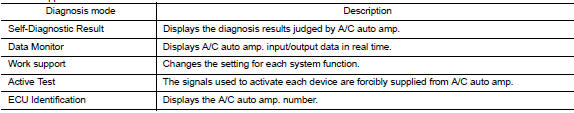
Description
Air conditioning system performs self-diagnosis, operation check, function diagnosis, and various settings using diagnosis function of each control unit.
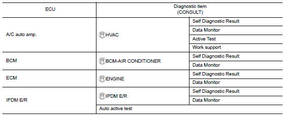
Consult Function (HVAC)
Consult can display each diagnosis item using the diagnosis test modes as shown.
Consult application items
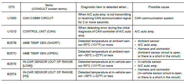
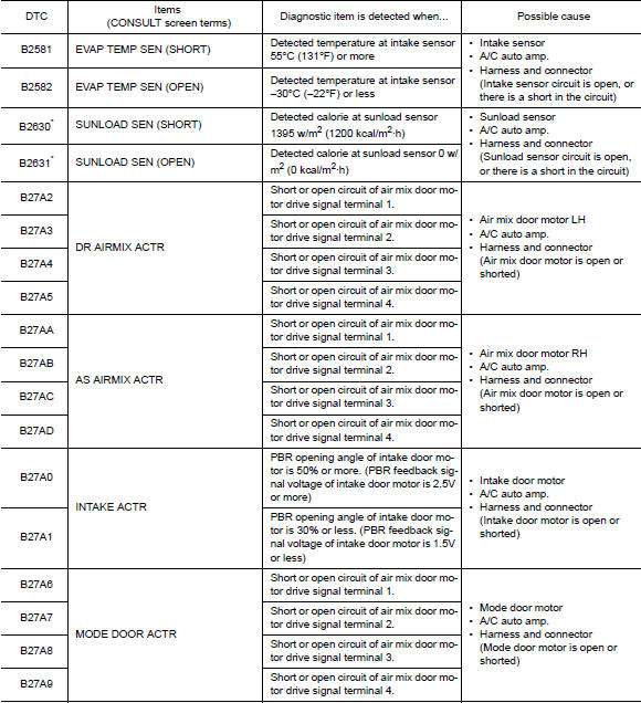
Self-diagnostic result
Refer to hac-38, "dtc index".
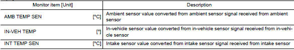
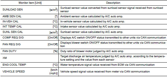
Display item list
*: Perform self-diagnosis under sunshine. When performing indoors, aim a light (more than 60 w) at sunload sensor, otherwise self-diagnosis reports an error even though the sunload sensor is functioning normally.
Data monitor
Display item list
Work support
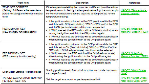
Note:
When the battery cable is disconnected from the negative terminal or when the battery voltage becomes 10v or less, the setting of work support may be cancelled.
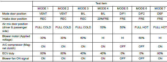
Active test
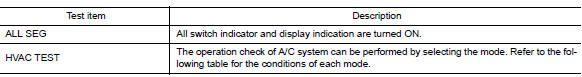
HVAC test
Note:
Perform the inspection of each output device after starting the engine, because the a/c compressor has been operating.
DIAGNOSIS SYSTEM (BCM)
Common item
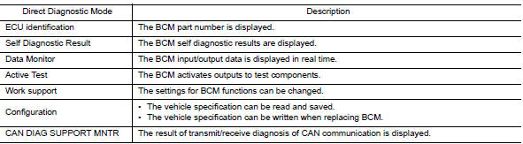
COMMON ITEM : CONSULT Function (BCM - COMMON ITEM)
Application item
Consult performs the following functions via can communication with bcm.
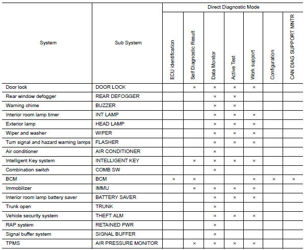
System application
BCM can perform the following functions.
Air conditioner
AIR CONDITIONER : CONSULT Function (BCM -AIR CONDITIONER)
Data monitor
DIAGNOSIS SYSTEM (IPDM E/R)
Diagnosis Description
AUTO ACTIVE TEST
Description
In auto active test, the ipdm e/r sends a drive signal to the following systems to check their operation.
- Front wiper (lo, hi)
- Parking lamp
- License plate lamp
- Tail lamp
- Front fog lamp (if equipped)
- Headlamp (lo, hi)
- A/C compressor (magnet clutch)
- Cooling fan
Operation Procedure
Note:
Never perform auto active test in the following conditions.
- Passenger door is open
- Consult is connected
- Close the hood and lift the wiper arms from the windshield. (Prevent windshield damage due to wiper operation)
Note:
When auto active test is performed with hood opened, sprinkle water on windshield beforehand.
- Turn the ignition switch off.
- Turn the ignition switch on, and within 20 seconds, press the driver door switch 10 times. Then turn the ignition switch off.
- Turn the ignition switch on within 10 seconds. After that the horn sounds once and the auto active test starts.
- After a series of the following operations is repeated 3 times, auto active test is completed.
Note:
- When auto active test has to be cancelled halfway through test, turn the ignition switch off.
- When auto active test is not activated, door switch may be the cause. Check door switch. Refer to DLK-103, "Component Inspection".
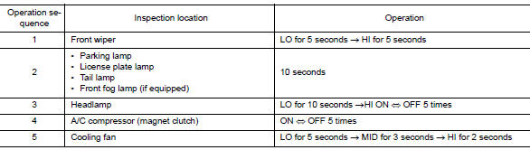
Inspection in auto active test
When auto active test is actuated, the following operation sequence is repeated 3 times.
Concept of auto active test
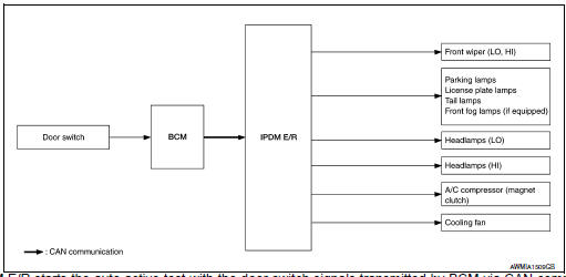
- Ipdm e/r starts the auto active test with the door switch signals
transmitted by bcm via can communication.
Therefore, the can communication line between ipdm e/r and bcm is considered normal if the auto active test starts successfully.
- The auto active test facilitates troubleshooting if any systems controlled by ipdm e/r cannot be operated.
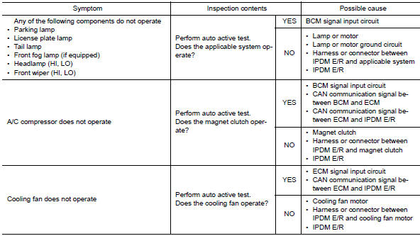
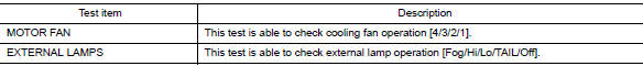
Diagnosis chart in auto active test
Consult Function (IPDM E/R)
APPLICATION ITEM
Consult performs the following functions via can communication with ipdm e/r.
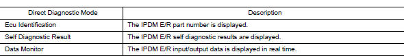
ECU Identification
The IPDM E/R part number is displayed.
SELF DIAGNOSTIC RESULT
Refer to PCS-20, "DTC Index".
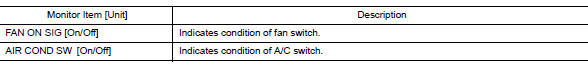
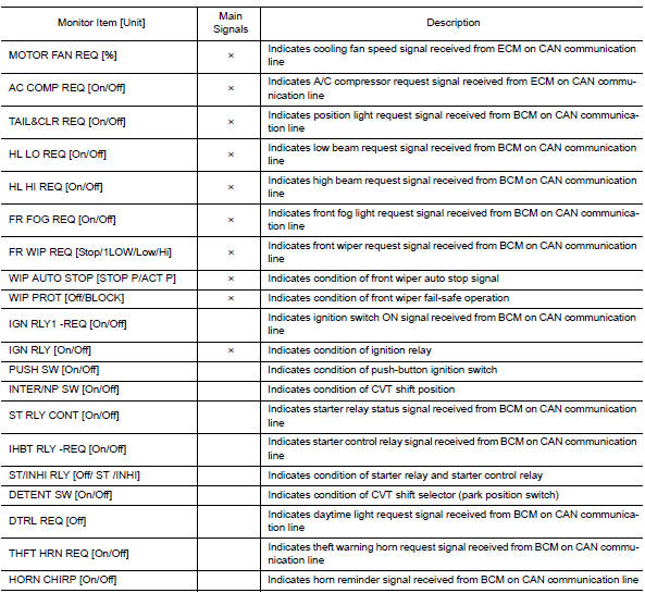
DATA MONITOR
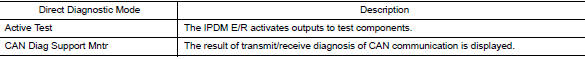
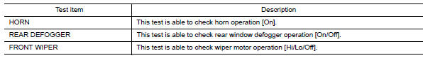
ACTIVE TEST
CAN DIAG SUPPORT MNTR
Refer to LAN-13, "CAN Diagnostic Support Monitor".
 Preparation
Special service tool
The actual shape of the tools may differ from those illustrated here.
Commercial service tool
...
 ECU diagnosis information
A/C AUTO AMP
Reference Value
VALUES ON THE DIAGNOSIS TOOL
TERMINAL LAYOUT
PHYSICAL VALUES
DTC Inspection Priority Chart
If some DTCs are displayed at the same time, perform ...
Other materials:
Roof side molding
Exploded view
Roof side molding
Roof side molding clip
Roof panel
Body side outer panel
Adhesive tape
Removal and installation
REMOVAL
ROOF SIDE MOLDING
Release roof side molding rear side clip, using a suitable tool
(A).
Clip
Front
CAUTION:
Apply protective tape ...
Main line between ipdm-e and dlc circuit
Diagnosis procedure
1.Check connector
Turn the ignition switch off.
Disconnect the battery cable from the negative terminal.
Check the following terminals and connectors for damage, bend and loose
connection (connector side
and harness side).
Harness connector e4
Harness connec ...
Engine room cover
Exploded View
Engine room cover
Mounting rubber (Black)
Mounting rubber (Gray)
Removal and Installation
REMOVAL
CAUTION:
Do not damage or scratch engine room cover when installing or removing.
Remove engine room cover by pulling straight up to release mounting rubber.
INSTALLATI ...
