Nissan Sentra Service Manual: Roof side molding
Exploded view
- Roof side molding
- Roof side molding clip
- Roof panel
- Body side outer panel
- Adhesive tape
Removal and installation
REMOVAL
ROOF SIDE MOLDING
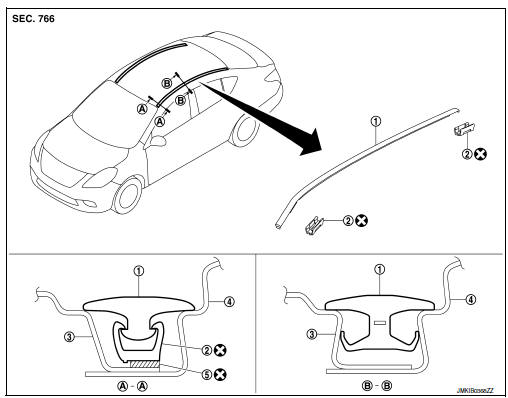
- Release roof side molding rear side clip, using a suitable tool (A).
 Clip
Clip
 Front
Front
CAUTION:
Apply protective tape (B) on body to protect the painted surface from damage.
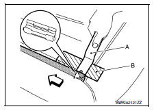
- Pull up roof side molding from rear end to front end.
 Front
Front
CAUTION:
Use care when pulling the roof side molding to avoid damaging.
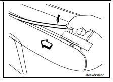
- Release windshield molding and clip at the front end of roof side molding, then remove while pulling toward vehicle rear.
 : Clip
REMOVAL OF ROOF SIDE MOLDING CLIPS
Heat adhesive tape using a heat gun and peel roof side molding clips (body side) using a suitable tool.
CAUTION:
Be careful not to damage the body.
INSTALLATION
- Clean tape removed surface with isopropyl alcohol or equivalent.
- Use two-part epoxy adhesive.
Adhesive : 3M-weld DP–100 or equivalent
- Apply adhesive evenly to clip tape surface.
Thickness : Approximately 0.5 mm (0.020 in)
- Position applied parts to the proper location, and then sufficiently press-fit until the adhesive protrudes to tape side.
Press-fit limit : 19.6 N× 2 seconds
- Tape roof side molding clips after press fit and temporarily hold it for specified time based on the following.
5 to 10В°C (41 to 50В°F) : 1 hour or more
11 to 23В°C (52 to 73В°F) : 30 minutes or more
24В°C or more (75В°F or more) : 15 minutes or more
CAUTION:
- Use double-sided tape after hardening for roof side molding clips.
- Securely insert molding rear end cap onto roof rear end cutout (installation standard).
- When installing roof side molding of windshield glass portion, check that body side molding fastener is securely inserted and then press in.
- Do not wash the vehicle within 24 hours so as to keep adhesive dry.
 Under cover
Front under cover
Front under cover : removal and installation
REMOVAL
Remove front side of front fender protector (LH/RH). Refer to EXT-28,
"FENDER PROTECTOR : Removal
and Installatio ...
 Drip molding
Exploded view
Drip molding
Clip
Removal and installation
REMOVAL
Release drip molding clips, then remove drip molding.
INSTALLATION
Installation is in the reverse order of removal. ...
Other materials:
Brakes
If the brakes do not operate properly, have the
brakes checked by a NISSAN dealer.
Self-adjusting brakes
Your vehicle is equipped with self-adjusting
brakes.
The front (and rear– if so equipped) disc-type
brakes self-adjust every time the brake pedal is
applied. The rear drum-type brakes ...
ABS Warning lamp
Component Function Check
1.CHECK ABS WARNING LAMP FUNCTION
Check that ABS warning lamp in combination meter turns ON for
approximately 2 seconds after ignition switch
is turned ON.
Is the inspection result normal?
YES >> Inspection End.
NO >> Proceed to diagnosis procedure. ...
Precaution
Precaution for Supplemental Restraint System (SRS) "AIR BAG" and "SEAT BELT
PRE-TENSIONER"
The supplemental restraint system such as “air bag” and “seat belt pre-tensioner”,
used along
with a front seat belt, helps to reduce the risk or severity of injur ...
