Nissan Sentra Service Manual: Main line between ipdm-e and dlc circuit
Diagnosis procedure
1.Check connector
- Turn the ignition switch off.
- Disconnect the battery cable from the negative terminal.
- Check the following terminals and connectors for damage, bend and loose connection (connector side and harness side).
- Harness connector e4
- Harness connector m2
Is the inspection result normal? YES >> GO TO 2.
NO >> Repair the terminal and connector.
2.Check harness continuity (open circuit)
- Disconnect the following harness connectors.
- IPDM E/R
- Harness connectors e4 and m2
- Check the continuity between the IPDM E/R harness connector and the harness connector.
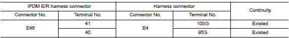
Is the inspection result normal? YES >> GO TO 3.
NO >> Repair the main line between the IPDM E/R and the harness connector E4.
3.Check harness continuity (open circuit)
Check the continuity between the harness connector and the data link connector.
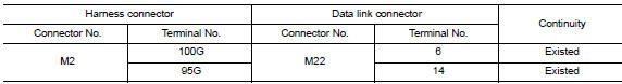
Is the inspection result normal? Yes (present error)>>check can system type decision again.
Yes (past error)>>error was detected in the main line between the ipdm e/r and the data link connector.
No >> repair the main line between the harness connector m2 and the data link connector.
 Can system (type 4)
Dtc/circuit diagnosis ...
 Main line between dlc and hvac circuit
Diagnosis Procedure
1.Check harness continuity (open circuit)
Turn the ignition switch OFF.
Disconnect the battery cable from the negative terminal.
Disconnect the following harness connector ...
Other materials:
Wiring diagram
SRS AIR BAG SYSTEM
Wiring Diagram
...
Steering column covers
Removal and Installation
REMOVAL
Remove the steering column cover screws (A), then remove the
steering column upper (1) and lower (2) covers.
NOTE:
Shown with steering wheel removed for clarity.
If necessary, rotate steering wheel to access steering column
cover screws (A).
...
Washer fluid level switch circuit
Description
Transmits the washer level switch signal to the combination meter.
Diagnosis procedure
Regarding Wiring Diagram information, refer to MWI-28, "Wiring Diagram".
1.Check washer level switch signal circuit
Turn ignition switch off.
Disconnect combination meter connecto ...
