Nissan Sentra B18 (2020-2025) Service Manual: System
System Description
System Description
-
Chassis control to integrally control the driving system was adopted.
-
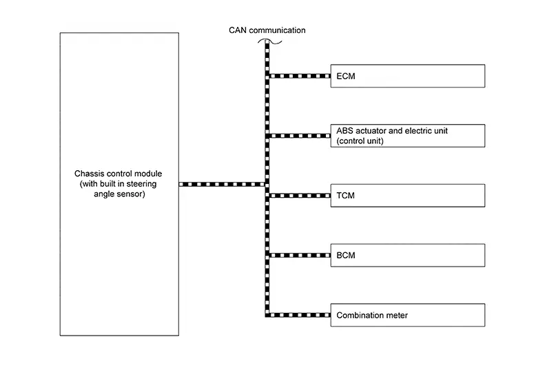
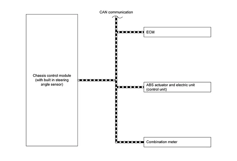
Chassis control module (with built in steering angle sensor) inputs the necessary information for control from CAN communication and each switch and integrally controls each system. Refer to the following table for systems controlled and input output signals.
|
Function |
Reference page |
|
|---|---|---|
|
Intelligent trace control function |
System Description |
|
|
Intelligent engine brake function |
System Description |
|
|
Active ride control function |
System Description |
|
SYSTEM DIAGRAM
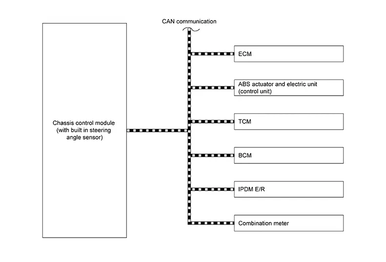
INPUT SIGNAL AND OUTPUT SIGNAL
Major signal transmission between each unit via communication lines is shown in the following table.
|
Component parts |
Signal description |
|---|---|
|
ECM |
Mainly transmits the following signals to chassis control module (with built in steering angle sensor) via CAN communication.
|
|
ABS actuator and electric unit (control unit) |
Mainly transmits the following signals to chassis control module (with built in steering angle sensor) via CAN communication.
Mainly receives the following signals from chassis control module (with built in steering angle sensor) via CAN communication.
|
|
TCM |
Mainly transmits the following signals to chassis control module (with built in steering angle sensor) via CAN communication.
Mainly receives the following signals from chassis control module (with built in steering angle sensor) via CAN communication.
|
|
BCM |
Mainly transmits the following signals to chassis control module (with built in steering angle sensor) via CAN communication.
|
|
IPDM E/R |
Mainly transmits the following signals to chassis control module (with built in steering angle sensor) via CAN communication.
|
|
Combination meter |
Mainly receives the following signals from chassis control module (with built in steering angle sensor) via CAN communication.
|
Fail-Safe [chassis Control Module (with Built in Steering Angle Sensor)]
Fail-Safe [Chassis Control Module (With Built In Steering Angle Sensor)]
|
DTC |
Fail-safe condition |
|---|---|
|
C1B80-54 |
The following functions are suspended.
|
|
C1B92-82 |
The following functions are suspended.
|
|
C1B96-82 |
Normal control |
|
C1BB4-44 |
The following functions are suspended.
|
|
C1BB4-46 |
|
|
C1BB4-47 |
|
|
C1BB4-49 |
|
|
C1BB4-52 |
|
|
C1BB5-1C |
|
|
U0076-00 |
|
|
U0078-00 |
|
|
U1A4A-87 |
|
|
U2140-87 |
|
|
U2141-87 |
|
|
U2148-83 |
|
|
U2148-87 |
|
|
U214E-87 |
Normal control |
|
U214F-87 |
|
|
U215B-87 |
|
|
U2252-83 |
Intelligent Trace Control Function
System Description
System Description
-
The steering operation condition by the driver and the information from multiple sensors are computed by the chassis control module (with built in steering angle sensor), and a command is transmitted to the ABS actuator and electric unit (control unit).
-
The ABS actuator and electric unit (control unit) controls the brake based on the command from the chassis control module (with built in steering angle sensor).
-
When cornering, driver operation is reduced and Nissan Sentra vehicle behavior is smoothened.
-
When the VDC function is turned OFF, the intelligent trace control function is also completely turned OFF.
-
When a malfunction occurs in intelligent trace control function, the master warning lamp illuminates and the information display in the combination meter informs the driver.

-
Intelligent trace control function may not be effective in all driving environments (traction conditions, etc.).
-
When intelligent trace control function operates, vibration may be transmitted to the brake pedal, an operation sound may be heard, and a feeling of deceleration may be felt. These are not symptoms of malfunctions and indicate normal operating conditions.
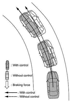
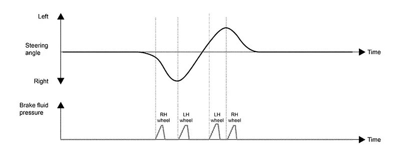
OPERATION CHARACTERISTICS
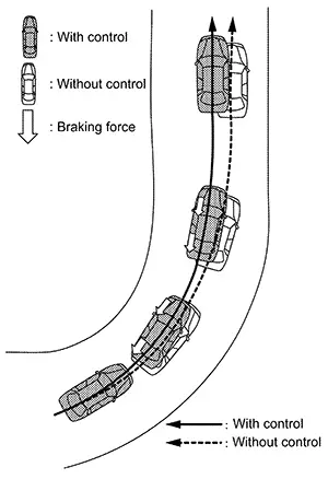
- This performs assistance when switching from deceleration
(brake operation) to acceleration (accelerator operation) when driving
on a curve. It operates the brake automatically to stabilize cornering
and smoothens acceleration in the longitudinal and lateral directions.
- The brake is controlled according to the steering
operation condition of the driver and the cornering condition of
the Nissan Sentra vehicle.
- The brake is controlled according to the steering
operation condition of the driver and the cornering condition of
the Nissan Sentra vehicle.
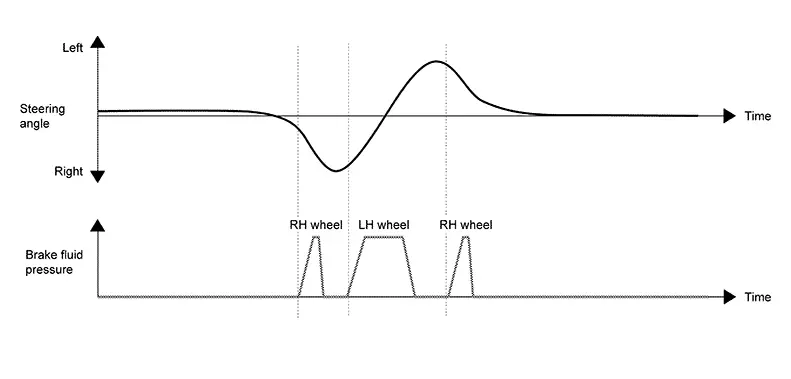
- For the purpose of improving responsiveness during
excessive steering operation, such as emergency avoidance steering,
etc., the brake is applied to the inside wheel of the steering direction
and causes turning momentum to be generated.
- The brake is controlled according to the steering
operation condition of the driver.
- The brake is controlled according to the steering
operation condition of the driver.
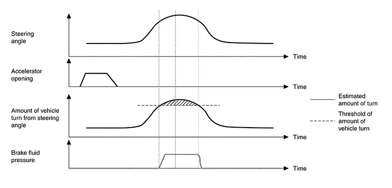
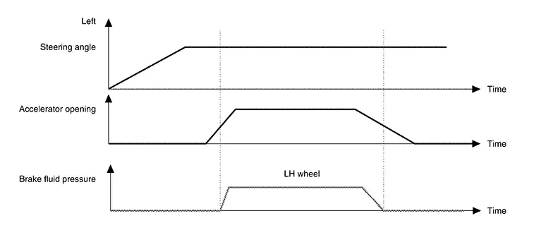
- When driving on a curve, change of the steering operation
angle is controlled, Nissan Sentra vehicle movement is smoothened and cornering with a
stable feeling is realized simultaneously by controlling the brake on
the inner wheel, according to accelerator operation.
- The brake is controlled according to the steering
operation condition of the driver and the cornering condition of
the Nissan Sentra vehicle.
- The brake is controlled according to the steering
operation condition of the driver and the cornering condition of
the Nissan Sentra vehicle.
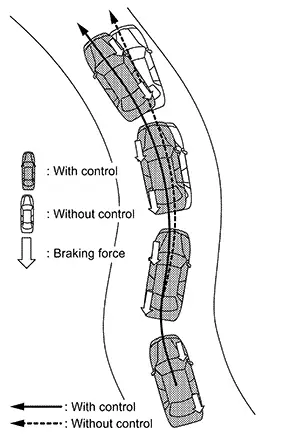
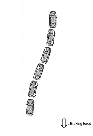
- When performing quick lane changes and other excessive
steering operations, the brake is operated automatically, and erratic
Nissan Sentra vehicle behavior due to steering operation is reduced.
- The brake is controlled according to the steering
operation condition of the driver and the cornering condition of
the Nissan Sentra vehicle.
- The brake is controlled according to the steering
operation condition of the driver and the cornering condition of
the Nissan Sentra vehicle.
SYSTEM DIAGRAM
INPUT SIGNAL AND OUTPUT SIGNAL
Major signal transmission between each unit via communication lines is shown in the following table.
|
Component parts |
Signal description |
|---|---|
|
ECM |
Mainly transmits the following signals to chassis control module (with built in steering angle sensor) via CAN communication.
|
|
ABS actuator and electric unit (control unit) |
Mainly transmits the following signals to chassis control module (with built in steering angle sensor) via CAN communication.
Mainly receives the following signals from chassis control module (with built in steering angle sensor) via CAN communication.
|
|
TCM |
Mainly transmits the following signals to chassis control module (with built in steering angle sensor) via CAN communication.
|
|
BCM |
Mainly transmits the following signals to chassis control module (with built in steering angle sensor) via CAN communication.
|
|
Combination meter |
Mainly receives the following signals from chassis control module (with built in steering angle sensor) via CAN communication.
|
Intelligent Engine Brake Function
System Description
System Description
-
The steering operation condition by the driver and the information from multiple sensors are computed by the chassis control module (with built in steering angle sensor), and a command is transmitted to the TCM.
-
Based on the command from the chassis control module (with built in steering angle sensor), TCM shifts the gear ratio of the transaxle to the low side and applies the engine brake.
-
When the VDC function is turned OFF, the intelligent engine brake function is also completely turned OFF.
-
When a malfunction occurs in intelligent engine brake function, the master warning lamp illuminates and the information display in the combination meter informs the driver.
-
Intelligent engine brake function may not be effective in all driving environments (traction conditions, etc.).
-
When intelligent engine brake function operates, the needle of the tachometer will rise up, you may hear an engine noise and sense slight deceleration. These are not symptoms of malfunctions and indicate normal operating conditions.
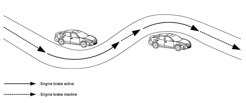
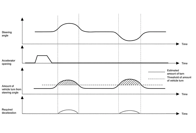
CORNERING CONTROL
-
For the purpose of reducing the operation of switching to depress the brake pedal during cornering, the operation information of the driver is computed by the chassis control module (with built in steering angle sensor) and a command is transmitted to TCM.
- Based on the command from the chassis control module (with
built in steering angle sensor) , TCM shifts the gear ratio of the
transaxle to the low side and applies the engine brake.
- The transaxle is controlled according to the
steering operation of the driver, as well as the accelerator
pedal condition and cornering condition of the Nissan Sentra vehicle.
- The transaxle is controlled according to the
steering operation of the driver, as well as the accelerator
pedal condition and cornering condition of the Nissan Sentra vehicle.
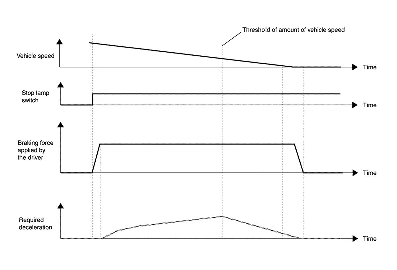
BRAKING CONTROL
-
For the purpose of improving the feeling of effectiveness of the brake when decelerating, the brake operation amount of the driver is computed by the chassis control module (with built in steering angle sensor) and a command is transmitted to TCM.
- Based on the command from the chassis control module (with
built in steering angle sensor), TCM shifts the gear ratio of the
transaxle to the low side and applies the engine brake.
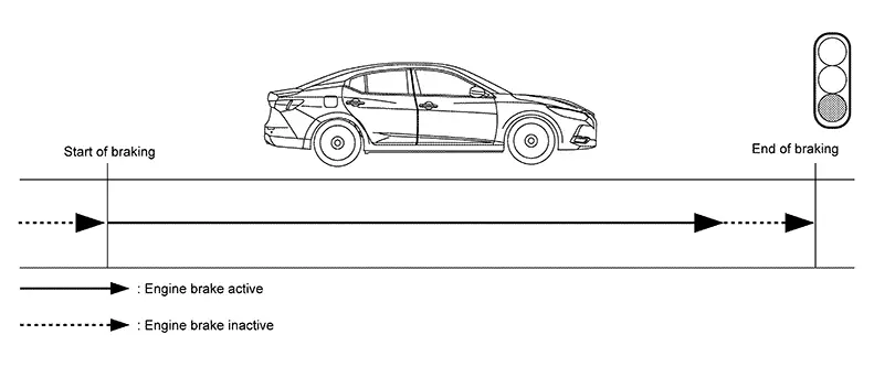
- The transaxle is controlled according to the brake
condition.
- The transaxle is controlled according to the brake
condition.
SYSTEM DIAGRAM
INPUT SIGNAL AND OUTPUT SIGNAL
Major signal transmission between each unit via communication lines is shown in the following table.
|
Component parts |
Signal description |
|---|---|
|
ECM |
Mainly transmits the following signals to chassis control module (with built in steering angle sensor) via CAN communication.
|
|
ABS actuator and electric unit (control unit) |
Mainly transmits the following signals to chassis control module (with built in steering angle sensor) via CAN communication.
|
|
TCM |
Mainly transmits the following signals to chassis control module (with built in steering angle sensor) via CAN communication.
Mainly receives the following signals from chassis control module (with built in steering angle sensor) via CAN communication.
|
|
BCM |
Mainly transmits the following signals to chassis control module (with built in steering angle sensor) via CAN communication.
|
|
Combination meter |
Mainly receives the following signals from chassis control module (with built in steering angle sensor) via CAN communication.
|
Active Ride Control Function
System Description
System Description
-
The driving condition and the information from multiple sensors are computed by the chassis control module (with built in steering angle sensor), and a command is transmitted to the ABS actuator and electric unit (control unit).
-
The ABS actuator and electric unit (control unit) control the brake based on the command from the chassis control module (with built in steering angle sensor).
-
When the VDC function is turned OFF, the active ride control function is also completely turned OFF.
-
When a malfunction occurs in active ride control function, the master warning lamp illuminates and the information display in the combination meter informs the driver.
Note:
-
Active ride control function may not be effective in all driving environments (traction conditions, etc.).
-
When active ride control function operates, vibration may be transmitted to the brake pedal, an operation sound may be heard, and a feeling of deceleration may be felt. These are not symptoms of malfunctions and indicate normal operating conditions.
-
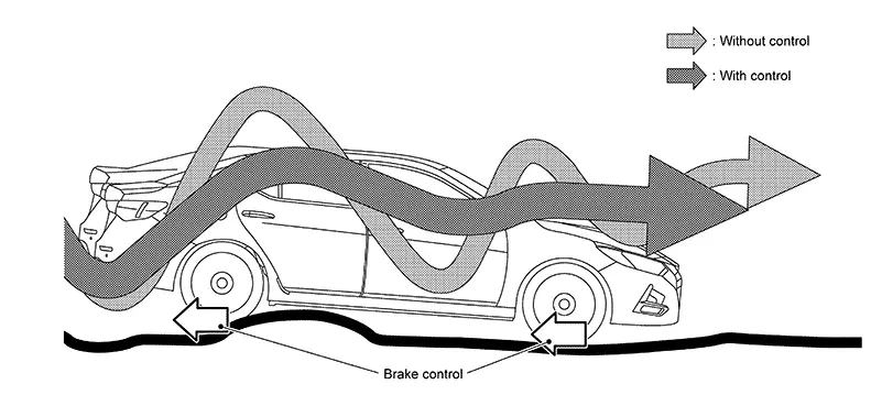
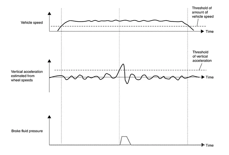
OPERATION CHARACTERISTICS
-
When driving on an uneven road surface, mainly the rotation speed information of each wheel is computed by the chassis control module (with built in steering angle sensor) to estimate vertical G, and a command is transmitted to the ABS actuator and electric unit (control unit).
-
The ABS actuator and electric unit (control unit) control brake fluid pressure (brake force) according to the command from the chassis control module (with built in steering angle sensor).
- By controlling the brake fluid pressure (brake force),
behavior of the Nissan Sentra vehicle in the vertical direction decreases, and riding
comfort is improved.
- Brake fluid pressure (brake force) is controlled
according to driving conditions.
- Brake fluid pressure (brake force) is controlled
according to driving conditions.
SYSTEM DIAGRAM
INPUT SIGNAL AND OUTPUT SIGNAL
Major signal transmission between each unit via communication lines is shown in the following table.
|
Component parts |
Signal description |
|---|---|
|
ECM |
Mainly transmits the following signals to chassis control module (with built in steering angle sensor) via CAN communication.
|
|
ABS actuator and electric unit (control unit) |
Mainly transmits the following signals to chassis control module (with built in steering angle sensor) via CAN communication.
Mainly receives the following signals from chassis control module (with built in steering angle sensor) via CAN communication.
|
|
Combination meter |
Mainly receives the following signals from chassis control module (with built in steering angle sensor) via CAN communication.
|
Information Display (combination Meter)
Chassis Control Display
Chassis Control Display
DESIGN/PURPOSE
The warning message is displayed on the information display when “Chassis Control” detected the system malfunction.
Warning Message
|
Design |
Warning message |
|---|---|
|
— |
Chassis Control System Error See Owner’s Manual |
SYNCHRONIZATION WITH MASTER WARNING LAMP
Applicable
SYNCHRONIZATION WITH WARNING CHIME
Not applicable
SYSTEM DIAGRAM
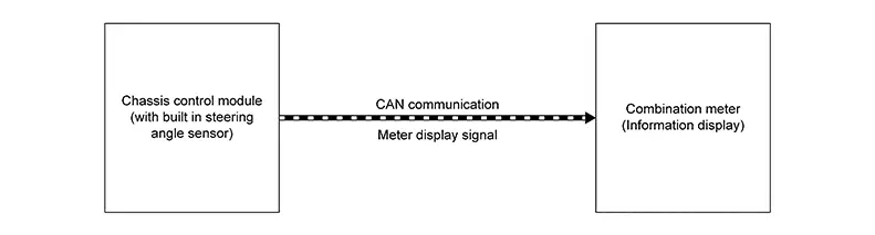
SIGNAL PATH
-
The chassis control module (with built in steering angle sensor) transmits the meter display signal to the combination meter via CAN communication.
-
The combination meter shows the chassis control warning on the information display, according to the signal.
WARNING MESSAGE DISPLAY CONDITION
When all of the following conditions are satisfied.
-
Ignition switch ON
-
Chassis control system malfunction is detected. Refer to DTC Index.
Other materials:
P0014 Evt Control
Dtc Description
DTC Description
DTC DETECTION LOGIC
DTC
CONSULT screen terms
(Trouble diagnosis
content)
DTC detection
condition
...
Security systems
Your Nissan Sentra may be equipped with two different types of security systems
designed to enhance vehicle protection and theft deterrence:
Vehicle security system (if so equipped)
NISSAN Vehicle Immobilizer System
Vehicle security system
The vehicle security system on the Nissan Se ...
System (power Door Lock System). System Description
System Description
System Description
INPUT SIGNAL AND OUTPUT SIGNAL
Signal name
Input
Output
Description
...