Nissan Sentra B18 (2020-2025) Service Manual: System
Intelligent Key System/engine Start Function
System Description
System Description
SYSTEM DIAGRAM
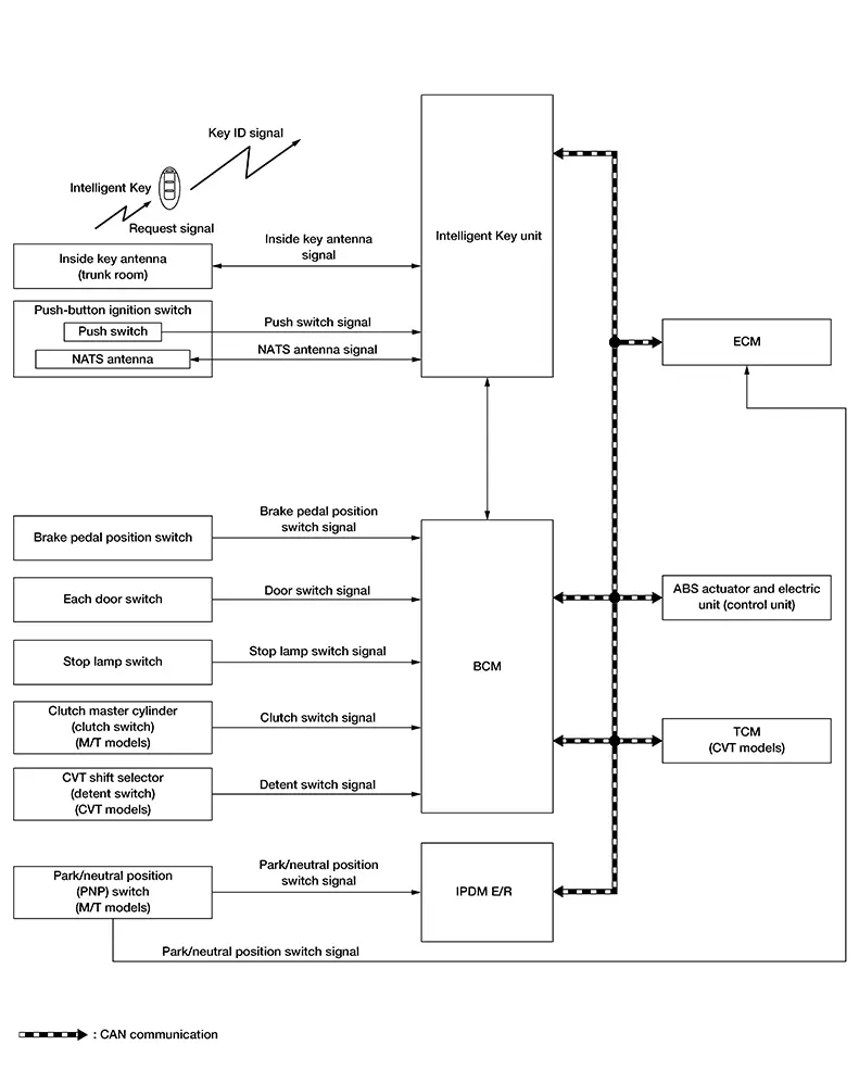
SIGNAL TRANSMISSION FUNCTION LIST
|
Signal name |
Input |
Output |
Description |
|---|---|---|---|
|
Inside key antenna signal |
Intelligent Key unit |
|
Inputs the inside key antenna signal via CAN communication |
|
ID verification signal |
Intelligent Key unit |
|
Inputs the ID verification signal via CAN communication |
|
Engine status signal |
ECM |
|
Inputs the engine status signal via CAN communication |
|
Push-button ignition switch status signal |
Intelligent Key unit |
BCM (CAN) |
Inputs the push-button ignition switch status signal via CAN communication |
|
Brake pedal position switch |
BCM |
Intelligent Key unit (CAN) |
Inputs the brake pedal position switch via CAN communication |
|
CVT shift select signal |
BCM |
TCM (CAN) |
Inputs the CVT shift select signal via CAN communication |
|
Stop lamp switch signal |
BCM |
|
Inputs the stop lamp switch signal via CAN communication |
|
Door switch signal |
BCM |
Intelligent Key unit (CAN) |
Inputs the door switch signal via CAN communication |
|
Nissan Sentra Vehicle speed signal |
ABS actuator and electric unit |
|
Inputs the engine status signal via CAN communication |
|
Park/neutral position switch signal |
ECM |
BCM (CAN) |
Inputs the park/neutral position switch signal via CAN communication |
|
Clutch switch signal |
BCM |
IPDM E/R (CAN) |
Inputs clutch switch signal via CAN communication |
SYSTEM DESCRIPTION
-
The engine start function of Intelligent Key system makes it possible to start and stop the engine without using the key, based on the electronic ID verification. The electronic ID verification is performed between Intelligent Key unit and Intelligent Key when the push-button ignition switch is pressed while the Intelligent Key is within the detection area of inside key antenna.
Note:
The driver should carry the Intelligent Key at all times.
-
Intelligent Key have ID (Key ID). It can perform the door lock/unlock operation and the push-button ignition switch operation when the registered Intelligent Key is carried.
-
If the ID is successfully verified, when push-button ignition switch is pressed, the engine can be started.
-
Up to 4 Intelligent Keys can be registered (Including the standard Intelligent Key) upon request from the customer.
PRECAUTIONS FOR INTELLIGENT KEY SYSTEM
The transponder (the chip for NATS ID verification) is integrated into the Intelligent Key. It is integrated into the mechanical key.) Therefore, ID verification cannot be performed by mechanical key only.
In that case, NATS ID verification can be performed when Intelligent Key backside is contacted to push-button ignition switch while brake pedal is depressed. If verification result is OK, engine can be started.
OPERATION WHEN INTELLIGENT KEY IS CARRIED
-
When the push-button ignition switch is pressed, the Intelligent Key unit activates the inside key antenna and transmits the request signal to the Intelligent Key.
-
The Intelligent Key receives the request signal and transmits the NATS ID signal to the Intelligent Key unit.
-
Intelligent Key unit receives the NATS ID signal verifies it with the registered ID.
-
When the ignition switch is placed to ON, Intelligent Key unit performs ID verification with the ECM. When the result is OK, engine start is permitted.
-
When ECM detects that the start engine conditions* are satisfied, it transmits a starter cut relay request signal to BCM.
-
When BCM receives a starter cut relay request signal from ECM, the starter cut relay is turned ON.
-
When starter cut relay is turned ON, IPDM E/R turns ON the starter relay and drives the starter motor.
-
When BCM receives an engine status signal from ECM, it turns the starter relay and starter cut relay OFF and stops cranking.
CAUTION:
When the Intelligent Key is carried outside of the Nissan Sentra vehicle (outside key antenna detection area) while the power supply is in the ON position, even if the engine start condition* is satisfied, the engine cannot be started.
*: For the engine start condition, refer to “IGNITION SWITCH POSITION CHANGE TABLE BY PUSH-BUTTON IGNITION SWITCH OPERATION”.
OPERATION RANGE
Engine can be started when Intelligent Key is inside the Nissan Sentra vehicle. However, sometimes engine may not start when Intelligent Key is on instrument panel or in glove box.
ENGINE START OPERATION WHEN INTELLIGENT KEY IS CONTACTED TO PUSH-BUTTON IGNITION SWITCH
When Intelligent Key battery is discharged, NATS ID verification between transponder in Intelligent Key and Intelligent Key unit is performed when Intelligent Key backside is contacted to push-button ignition switch while brake pedal is depressed. If the verification result is OK, engine can be started.
IGNITION SWITCH POSITION CHANGE TABLE BY PUSH-BUTTON IGNITION SWITCH OPERATION
The ignition switch position can be changed by the following operations.
Note:
-
When an Intelligent Key is within the detection area of inside key antenna or when Intelligent Key backside is contacted to push-button ignition switch, it is equivalent to the operations below.
-
When starting the engine, the BCM monitors under the engine start conditions,
CVT models
-
Brake pedal operation condition
-
Selector lever position
-
Nissan Sentra Vehicle speed
M/T models
-
Brake pedal operation condition
-
Clutch pedal operation condition
-
Nissan Sentra Vehicle speed
-
Vehicle speed: less than 2.5 MPH (4 km/h)
|
Power supply position |
Condition |
Push-button ignition switch operation frequency |
|||||
|---|---|---|---|---|---|---|---|
|
CVT models |
M/T models |
||||||
|
Selector lever |
Brake pedal operation condition |
Normal condition |
Special condition |
||||
|
Shift lever |
Clutch pedal operation condition |
Shift lever |
Brake pedal operation condition |
||||
|
LOCK → ON |
— |
Not depressed |
— |
Not depressed |
— |
Not depressed |
1 |
|
LOCK → ON → OFF |
— |
Not depressed |
— |
Not depressed |
— |
Not depressed |
2 |
|
LOCK → START ON → START |
P or N position |
Depressed |
— |
Depressed |
Neutral |
Depressed |
1 |
|
Engine is running → LOCK |
— |
— |
— |
— |
— |
— |
1 |
If the Intelligent Key unit cannot detect that the Intelligent Key is in the Nissan Sentra vehicle, ignition switch can be placed OFF by the press and hold the push-button ignition switch for 2 seconds or more.
Nissan Sentra Vehicle speed: 2.5 MPH (4 km/h) or more
|
Power supply position |
Condition |
Push-button ignition switch operation frequency |
|||||
|---|---|---|---|---|---|---|---|
|
CVT models |
M/T models |
||||||
|
Selector lever |
Brake pedal operation condition |
Normal condition |
Special condition |
||||
|
Shift lever |
Clutch pedal operation condition |
Shift lever |
Brake pedal operation condition |
||||
|
Engine is running → OFF |
— |
— |
— |
— |
— |
— |
Emergency stop operation |
|
Engine stall return operation while driving |
N position |
Not depressed |
— |
Depressed |
Neutral |
— |
1 |
Emergency stop operation
-
Press and hold the push-button ignition switch for 2 seconds or more.
-
Press the push-button ignition switch 3 times or more within 1.5 seconds.
Nissan Anti-Theft System
System Description
System Description
SYSTEM DIAGRAM
SIGNAL TRANSMISSION FUNCTION LIST
|
Signal name |
Input |
Output |
Description |
|---|---|---|---|
|
Inside key antenna signal |
Intelligent Key unit |
|
Inputs the inside key signal antenna signal via CAN communication |
|
ID verification signal |
Intelligent Key unit |
|
Inputs the ID verification signal via CAN communication |
|
Engine status signal |
ECM |
|
Inputs the engine status signal via CAN communication |
|
Push-button ignition switch status signal |
Intelligent Key unit |
BCM (CAN) |
Inputs the push-button ignition switch status signal via CAN communication |
|
Brake pedal position switch |
BCM |
Intelligent Key unit (CAN) |
Inputs the brake pedal position switch via CAN communication |
|
CVT shift select signal |
BCM |
|
Inputs the CVT shift select signal via CAN communication |
|
Stop lamp switch signal |
BCM |
|
Inputs the stop lamp switch signal via CAN communication |
|
Door switch signal |
BCM |
|
Inputs the door switch signal via CAN communication |
SYSTEM DESCRIPTION
-
The NISSAN ANTI-THEFT SYSTEM (NATS) prevents the engine from being started by Intelligent Key whose ID is not registered to the Nissan Sentra vehicle (Intelligent Key unit). It has higher protection against auto theft involving the duplication of mechanical keys.
-
The ignition key integrated in the Intelligent Key cannot start the engine. When the Intelligent Key battery is discharged, the NATS ID verification is performed between the transponder integrated with Intelligent Key and Intelligent Key unit via NATS antenna. when the Intelligent Key backside is contacted to push-button ignition switch while brake pedal is depressed. If the verification result is OK, the engine start operation can be performed by the push-button ignition switch operation.
-
Up to 4 Intelligent Keys can be registered (including the standard ignition key) upon request from the owner.
-
When replacing ECM, Intelligent Key unit or Intelligent Key, the specified procedure (Initialization and registration) using CONSULT is required.
PRECAUTIONS FOR KEY REGISTRATION
The ID registration is a procedure that erases the current NATS ID once, and then registers a new ID. Therefore before starting the registration operation, collect all registered Intelligent Keys from the customer.
ENGINE START OPERATION WHEN INTELLIGENT KEY IS CONTACTED TO PUSH-BUTTON IGNITION SWITCH
-
When brake pedal is depressed while selector lever is in the P position, Intelligent Key unit activates NATS antenna that is located behind push-button ignition switch.
-
When Intelligent Key (transponder built-in) backside is contacted to push-button ignition switch, Intelligent Key unit starts NATS ID verification between Intelligent Key unit and Intelligent Key (transponder built-in) via NATS antenna.
-
When NATS ID verification result is OK, buzzer in combination meter sounds.
-
When the ignition switch is placed to ON, Intelligent Key unit performs ID verification with the ECM. When the result is OK, engine start is permitted.
-
BCM detects that the selector lever position and brake pedal operation condition.
-
When ECM detects that the start engine conditions* are satisfied, it transmits a starter cut relay request signal to BCM.
-
When BCM receives a starter cut relay request signal from ECM, the starter cut relay is turned ON.
-
When starter cut relay is turned ON, IPDM E/R turns ON the starter relay and drives the starter motor.
-
When BCM receives an engine status signal from ECM, it turns the starter relay and starter cut relay OFF and stops cranking.
*: For the engine start condition, refer to “IGNITION SWITCH POSITION CHANGE TABLE BY PUSH-BUTTON IGNITION SWITCH OPERATION” below.
IGNITION SWITCH POSITION CHANGE TABLE BY PUSH-BUTTON IGNITION SWITCH OPERATION
The ignition switch position can be changed by the following operations.
Note:
-
When an Intelligent Key is within the detection area of inside key antenna or when Intelligent Key backside is contacted to push-button ignition switch, it is equivalent to the operations below.
-
When starting the engine, the BCM monitors under the engine start conditions.
CVT models
-
Brake pedal operation condition
-
Selector lever position
-
Nissan Sentra Vehicle speed
M/T models
-
Brake pedal operation condition
-
Clutch pedal operation condition
-
Nissan Sentra Vehicle speed
-
Vehicle speed: less than 2.5 MPH (4 km/h)
|
Power supply position |
Condition |
Push-button ignition switch operation frequency |
|||||
|---|---|---|---|---|---|---|---|
|
CVT models |
M/T models |
||||||
|
Selector lever |
Brake pedal operation condition |
Normal condition |
Special condition |
||||
|
Shift lever |
Clutch pedal operation condition |
Shift lever |
Brake pedal operation condition |
||||
|
LOCK → ON |
— |
Not depressed |
— |
Not depressed |
— |
Not depressed |
1 |
|
LOCK → ON → OFF |
— |
Not depressed |
— |
Not depressed |
— |
Not depressed |
2 |
|
LOCK → START ON → START |
P or N position |
Depressed |
— |
Depressed |
Neutral |
Depressed |
1 |
|
Engine is running → LOCK |
— |
— |
— |
— |
— |
— |
1 |
If the Intelligent Key unit cannot detect that the Intelligent Key is in the Nissan Sentra vehicle, ignition switch can be placed OFF by the press and hold the push-button ignition switch for 2 seconds or more.
Nissan Sentra Vehicle speed: 2.5 MPH (4 km/h) or more
|
Power supply position |
Condition |
Push-button ignition switch operation frequency |
|||||
|---|---|---|---|---|---|---|---|
|
CVT models |
M/T models |
||||||
|
Selector lever |
Brake pedal operation condition |
Normal condition |
Special condition |
||||
|
Shift lever |
Clutch pedal operation condition |
Shift lever |
Brake pedal operation condition |
||||
|
Engine is running → OFF |
— |
— |
— |
— |
— |
— |
Emergency stop operation |
|
Engine stall return operation while driving |
N position |
Not depressed |
— |
Depressed |
Neutral |
— |
1 |
Emergency stop operation
-
Press and hold the push-button ignition switch for 2 seconds or more.
-
Press the push-button ignition switch 3 times or more within 1.5 seconds.
Vehicle Security System
System Description
System Description
SYSTEM DIAGRAM
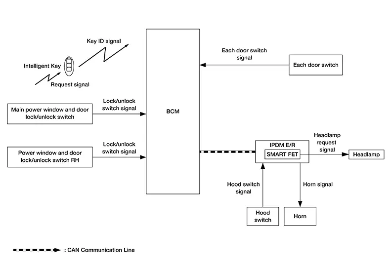
SIGNAL TRANSMISSION FUNCTION LIST
|
Signal name |
Input |
Output |
Description |
|---|---|---|---|
|
Lock/unlock switch signal |
BCM |
IPDM E/R (CAN) |
Inputs the lock/unlock switch signal via CAN communication |
|
Each door switch signal |
BCM |
IPDM E/R (CAN) |
Inputs the door switch via CAN communication |
|
Hood switch signal |
IPDM E/R |
BCM (CAN) |
Inputs the hood switch signal via CAN communication |
SYSTEM DESCRIPTION
-
The Nissan Sentra vehicle security system has two alarm functions (theft warning alarm and panic alarm) and reduces the possibility of a theft or mischief by activating horns and headlamps intermittently.
-
The panic alarm does not start when the theft warning alarm is activating and the panic alarm stops when the theft warning alarm is activated.
The priority of the functions are as per the following.
Priority
Function
1
Theft warning alarm
2
Panic alarm
THEFT WARNING ALARM
The theft warning alarm function activates horns and headlamps intermittently when BCM detects that any door is opened by unauthorized means while the system is in the ARMED state.
Operation Flow
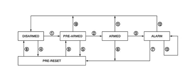
|
No. |
System state |
Switching condition |
||
|---|---|---|---|---|
|
1 |
DISARMED to PRE-ARMED |
When all conditions of A and one condition of B is satisfied. |
A |
B |
|
All doors are locked by:
|
|||
|
2 |
PRE-ARMED to ARMED |
When all of the following conditions are satisfied for 30 seconds. |
|
|
|
3 |
ARMED to ALARM |
When one condition of A and one condition of B are satisfied. |
A |
B |
|
Intelligent Key: Not used |
|
|||
|
4 |
DISARMED to PRE-RESET |
No conditions |
||
|
5 |
PRE-ARMED to PRE-RESET |
|||
|
6 |
ARMED to PRE-RESET |
|||
|
7 |
ALARM to PRE-RESET |
|||
|
8 |
PRE-RESET to DISARMED |
|||
|
9 |
PRE-RESET to PRE-ARMED |
|||
|
10 |
PRE-ARMED to DISARMED |
When one of the following conditions is satisfied. |
|
|
|
11 |
ARMED to DISARMED |
When one of the following conditions is satisfied. |
|
|
|
12 |
ALARM to DISARMED |
|||
|
13 |
RE-ALARM |
When one of the following conditions is satisfied after the ALARM operation is finished. |
|
|
-
To lock/unlock all doors by operating remote controller button of Intelligent Key or door request switch, Intelligent Key must be within the detection area of outside key antenna. For details, refer to System Description.
-
To open trunk by operating trunk opener switch, Intelligent Key must be within the detection area of outside key antenna. For details, refer to System Description.
DISARMED Phase
The Nissan Sentra vehicle security system is not set in the DISARMED phase. The vehicle security system stays in this phase while any door is open because it is assumed that the owner is inside or nearby the Nissan Sentra vehicle.
When the vehicle security system is reset, each phase switches to the DISARMED phase directly.
PRE-ARMED Phase
The PRE-ARMED phase is the transient state between the DISARMED phase and the ARMED phase. This phase is maintained for 30 seconds so that the owner can reset the setting due to a mis-operation. This phase switches to the ARMED phase when Nissan Sentra vehicle conditions are not changed for 30 seconds.
To reset the PRE-ARMED phase, refer to the switching condition of No. 10 in the table above.
ARMED Phase
The Nissan Sentra vehicle security system is set and BCM monitors all necessary inputs. If any door is opened without using Intelligent Key, Nissan Sentra vehicle security system switches to the ALARM phase.
To reset the ARMED phase, refer to the switching condition of No. 11 in the table above.
ALARM Phase
BCM transmits “Theft Warning Horn Request” signal and “High Beam Request” signal intermittently to IPDM E/R via CAN communication. In this phase, horns and headlamps are activated intermittently for approximately 50 seconds to warn that the Nissan Sentra vehicle is accessed by unauthorized means. ON/OFF timing of horns and headlamps are synchronized. After 50 seconds, the Nissan Sentra vehicle security system returns to the ARMED phase. At this time, if BCM still detects unauthorized access to the Nissan Sentra vehicle, the system is switched to the ALARM phase again. This RE-ALARM operation is carried out a maximum of 2 times.
To cancel the ALARM operation, refer to the switching condition of No. 12 in the table above.
Note:
If a battery terminal is disconnected during the ALARM phase, theft warning alarm stops. But when the battery terminal is reconnected, theft warning alarm is activated again.
PANIC ALARM
-
The panic alarm function activates horns and headlamps intermittently when the owner presses the PANIC ALARM button of Intelligent Key outside the Nissan Sentra vehicle while the power supply position is OFF or LOCK.
-
When Intelligent Key Unit receives panic alarm signal from Intelligent Key, BCM transmits “Theft Warning Horn Request” signal and “High Beam Request” signal intermittently to IPDM E/R via CAN communication. To prevent the activation due to mis-operation of Intelligent Key by owner, the panic alarm function is activated when Intelligent Key Unit receives the signal for 0.4 - 0.6 seconds.
-
Panic alarm operation is maintained for 25 seconds.
-
Panic alarm operation is cancelled when BCM receives one of the following signals:
-
LOCK button of Intelligent Key: ON
-
UNLOCK button of Intelligent Key: ON
-
PANIC ALARM button of Intelligent Key: Long pressed
-
Any door request switch: ON
-
Other materials:
Front Grille
Exploded View
Exploded View
1.
Front grille
2.
Emblem
3.
Front bumper ...
P0171 Fuel Injection System Function
Dtc Description
DTC Description
With the Air/Fuel Mixture Ratio Self-Learning Control, the actual
mixture ratio can be brought closely to the theoretical mixture ratio based on
the mixture ratio feedback signal from A/F sensor 1. The ECM calculatesthe
necessary compensation to corre ...
B24d4-08 A/c Control Comm
Dtc Description
DTC Description
DTC DETECTION LOGIC
DTC No.
CONSULT screen terms
(Trouble diagnosis content)
DTC detection condition
...