Nissan Sentra Owners Manual: Supplemental air bag warning light
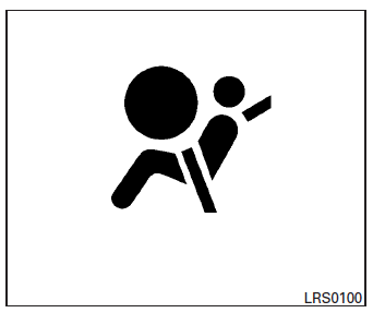
The supplemental air bag warning light,
displaying  in the instrument panel,
monitors
the circuits for the air bag systems, pretensioners
and all related wiring.
When the ignition switch is placed in the ON or START position, the supplemental air bag warning light illuminates for about 7 seconds and then turns off. This means the system is operational.
If any of the following conditions occur, the front air bag, side air bag, curtain air bag and pretensioner systems need servicing:
- The supplemental air bag warning light remains on after approximately 7 seconds.
- The supplemental air bag warning light flashes intermittently.
- The supplemental air bag warning light does not come on at all.
Under these conditions, the front air bag, side air bag, curtain air bag or pretensioner systems may not operate properly. They must be checked and repaired. Take your vehicle to the nearest NISSAN dealer.
| WARNING If the supplemental air bag warning light is on, it could mean that the front air bag, side air bag, curtain air bag and/or pretensioner systems will not operate in an accident. To help avoid injury to yourself or others, have your vehicle checked by a NISSAN dealer as soon as possible. |
Repair and replacement procedure
The front air bags, side air bags, curtain air bags and pretensioners are designed to inflate on a one-time-only basis. As a reminder, unless it is damaged, the supplemental air bag warning light remains illuminated after inflation has occurred.
Repair and replacement of these supplemental air bag systems should be done only by a NISSAN dealer.
When maintenance work is required on the vehicle, the front air bags, side air bags, curtain air bags, pretensioners and related parts should be pointed out to the person performing the maintenance.
The ignition switch should always be placed in the LOCK position when working under the hood or inside the vehicle.
WARNING
|
NOTE:
In the event of a crash involving an airbag deployment (side, front or both), the vehicle’s hazard lamps (turn indicators) will activate.
 Supplemental air bag warning labels
SRS Front Air Bag Warning Labels
Warning labels about the supplemental frontimpact
air bag system are placed in the vehicle as
shown in the illustration. ...

Other materials:
A-bag branch line circuit
Diagnosis procedure
Warning:
Always observe the following items for preventing accidental
activation.
Before servicing, turn ignition switch off, disconnect battery
negative terminal, and wait 3 minutes
or more. (To discharge backup capacitor.)
Never use unspecified tester or other me ...
Basic inspection
DIAGNOSIS AND REPAIR WORKFLOW
Work Flow
OVERALL SEQUENCE
DETAILED FLOW
1.INTERVIEW CUSTOMER
Interview the customer to obtain as much information as possible about the
conditions and environment under
which the malfunction occurred.
>> GO TO 2.
2.SYMPTOM CHECK
Verify symptoms.
...
Dtc/circuit diagnosis
Eco mode switch
Component function check
1. Check eco mode switch operation
Turn ignition switch ON.
Check ECO mode indicator lamp turns ON/OFF on combination meter when
turn ECO mode switch ON/
OFF.
Is the inspection result normal?
Yes >> inspection end
No >> go to dm ...
