Nissan Sentra Service Manual: Brake pedal position switch
Component Function Check
1.CHECK BRAKE PEDAL POSITION SWITCH FUNCTION
 With CONSULT
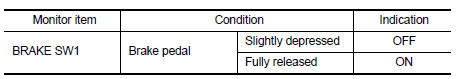
- Turn ignition switch ON.
- Select “ENGINE” using CONSULT.
- Select “BRAKE SW1” in “DATA MONITOR” mode.
- Check “BRAKE SW1” indication under the following conditions.
 Without CONSULT
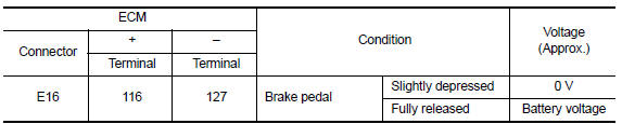
- Turn ignition switch ON.
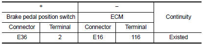
- Check the voltage between ECM harness connector terminals under the following conditions.
Is the inspection result normal? YES >> INSPECTION END
NO >> Proceed to EC-446, "Diagnosis Procedure".
Diagnosis Procedure
1.CHECK BRAKE PEDAL POSITION SWITCH POWER SUPPLY CIRCUIT
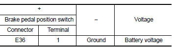
- Turn ignition switch OFF.
- Disconnect brake pedal position switch harness connector.
- Turn ignition switch ON.
- Check the voltage between brake pedal position switch harness connector and ground.
Is the inspection result normal? YES >> GO TO 3.
NO >> GO TO 2.
2.CHECK STOP LAMP SWITCH POWER SUPPLY CIRCUIT
- Pull out #5 fuse.
- Check that the fuse is not fusing.
- Check the continuity between stop lamp switch harness connector and fuse terminal.
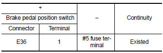
- Also check harness for short to ground and short to power.
Is the inspection result normal? YES >> Check power supply circuit for 12V battery power supply.
NO >> Repair or replace error-detected parts.
3.CHECK BRAKE PEDAL POSITION SWITCH INPUT SIGNAL CIRCUIT
- Turn ignition switch OFF.
- Disconnect ECM harness connector.
- Check the continuity between brake pedal position switch harness connector and ECM harness connector.
- Also check harness for short to ground and short to power.
Is the inspection result normal? YES >> GO TO 4.
NO >> Repair or replace error-detected parts.
4.CHECK BRAKE PEDAL POSITION SWITCH
Check brake pedal position switch. Refer to EC-447, "Component Inspection (Brake Pedal Position Switch)" Is the inspection result normal? YES >> Check intermittent incident. Refer to GI-39, "Intermittent Incident".
NO >> Replace brake pedal position switch. Refer to BR-22, "Exploded View".
Component Inspection (Brake Pedal Position Switch)
1.CHECK BRAKE PEDAL POSITION SWITCH-I
- Turn ignition switch OFF.
- Disconnect brake pedal position switch harness connector.
- Check the continuity between brake pedal position switch terminals under the following conditions.
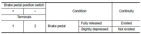
Is the inspection result normal? YES >> INSPECTION END
NO >> GO TO 2.
2.CHECK BRAKE PEDAL POSITION SWITCH-II
- Adjust brake pedal position switch installation. Refer to BR-15, "Adjustment".
- Check the continuity between brake pedal position switch terminals under the following conditions.
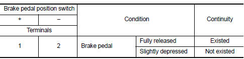
Is the inspection result normal? YES >> INSPECTION END
NO >> Replace brake pedal position switch. Refer to BR-22, "Exploded View".
 Sensor power supply 2 circuit
Description
ECM supplies a voltage of 5.0 V to some of the sensors systematically divided
into 2 groups, respectively.
Accordingly, when a short circuit develops in a sensor power source, a
ma ...
 ASCD Indicator
Component Function Check
1.CHECK ASCD INDICATOR FUNCTION
Check ASCD indicator under the following conditions.
ASCD INDICATOR
CONDITION
SPECIFICATION
CRUISE LAMP
Ig ...
Other materials:
Oil seal
Valve oil seal : Removal and Installation
REMOVAL
Rotate crankshaft, and set piston whose valve oil seal is to be removed
to TDC. This will prevent valve
from dropping into cylinder.
CAUTION:
When rotating crankshaft, be careful to avoid scarring front cover with
timing chain.
Re ...
Sensor power supply 2 circuit
Description
ECM supplies a voltage of 5.0 V to some of the sensors systematically divided
into 2 groups, respectively.
Accordingly, when a short circuit develops in a sensor power source, a
malfunction may occur simultaneously
in the sensors belonging to the same group as the shorted-circui ...
How to use the touch-screen
CAUTION
The glass display screen may break if it
is hit with a hard or sharp object. If the
glass screen breaks, do not touch it.
Doing so could result in an injury.
To clean the display, never use a rough
cloth, alcohol, benzine, thinner or any
kind of solvent or paper towel with a
chemic ...
