Nissan Sentra Service Manual: Sensor power supply 2 circuit
Description
ECM supplies a voltage of 5.0 V to some of the sensors systematically divided into 2 groups, respectively.
Accordingly, when a short circuit develops in a sensor power source, a malfunction may occur simultaneously in the sensors belonging to the same group as the shorted-circuit sensor.
Sensor power supply 1
- Battery current sensor
- Crankshaft position (CKP) sensor (POS)
- Throttle position (TP) sensor
- Accelerator pedal position (APP) sensor 1
NOTE:
If sensor power supply 1 circuit is malfunctioning, DTC P0643 is displayed.
Sensor power supply 2
- Camshaft position (CMP) sensor (PHASE)
- Mass air flow (MAF) sensor
- Engine oil pressure (EOP) sensor
- Exhaust valve timing (EVT) control position sensor
- Accelerator pedal position (APP) sensor 2
- Intake manifold runner control valve position sensor
Diagnosis Procedure
1.CHECK ACCELERATOR PEDAL POSITION SENSOR 2 POWER SUPPLY CIRCUIT-1
- Turn ignition switch OFF.
- Disconnect accelerator pedal position (APP) sensor harness connector.
- Turn ignition switch ON.
- Check the voltage between APP sensor harness connector and ground.
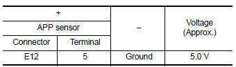
Is the inspection result normal? YES >> GO TO 4.
NO >> GO TO 2.
2.CHECK ACCELERATOR PEDAL POSITION SENSOR 2 POWER SUPPLY CIRCUIT-2
- Turn ignition switch OFF.
- Disconnect ECM harness connector.
- Turn ignition switch ON.
- Check the continuity between APP sensor harness connector and ECM.
CVT models
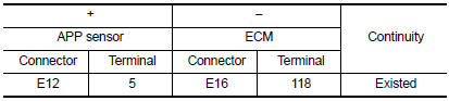
Is the inspection result normal? YES >> GO TO 3.
NO >> Repair or replace error-detected parts.
3.CHECK SENSOR POWER SUPPLY CIRCUITS
Check harness for short to power and short to ground, between the following terminals.
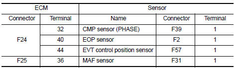
Is the inspection result normal? YES >> GO TO 4.
NO >> Repair or replace error-detected parts.
4.CHECK COMPONENTS
Check the following.
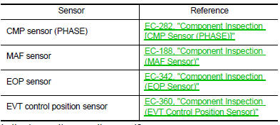
Is the inspection result normal? YES >> GO TO 5.
NO >> Repair or replace malfunctioning component.
5.CHECK APP SENSOR
Check APP sensor. Refer to EC-436, "Component Inspection (APP Sensor)".
Is the inspection result normal? YES >> Check intermittent incident. Refer to GI-39, "Intermittent Incident".
NO >> Replace accelerator pedal assembly. Refer to ACC-3, "Removal and Installation".
 P2138 APP Sensor
DTC Logic
DTC DETECTION LOGIC
NOTE:
If DTC P2138 is displayed with DTC P0643, first perform the trouble
diagnosis for DTC P0643. Refer to
EC-353, "DTC Logic".
DTC No.
CONSUL ...
 Brake pedal position switch
Component Function Check
1.CHECK BRAKE PEDAL POSITION SWITCH FUNCTION
With CONSULT
Turn ignition switch ON.
Select “ENGINE” using CONSULT.
Select “BRAKE SW1” in “DA ...
Other materials:
C1105, C1106, C1107, C1108 Wheel sensor
Description
When the sensor rotor rotates, the magnetic field changes. It
converts the magnetic field changes to current
signals (rectangular wave) and transmits them to the ABS actuator and electric
unit (control unit).
DTC Logic
DTC DETECTION LOGIC
DTC
Display Item
Malfunct ...
Low tire pressure warning lamp does not turn oFF
Low Tire Pressure Warning Lamp Stays On When Ignition Switch Is Turned On
DIAGNOSTIC PROCEDURE
1.INSPECT BCM CONNECTOR
Turn ignition switch OFF.
Disconnect BCM connectors.
Check terminals for damage or loose connections.
Is the inspection result normal?
YES >> GO TO 2.
NO > ...
Rear rh side power window does not operate
When both power window main switch and rear power window switch RH are
operated
When both power window main switch and rear power window switch rh are
operated : diagnosis procedure
1.CHECK REAR POWER WINDOW SWITCH RH
Check rear power window switch RH.
Refer to PWC-40, "REAR POWER WIN ...
