Nissan Sentra Service Manual: Power supply and ground circuit
Av control unit
Av control unit : diagnosis procedure
Regarding wiring diagram information, refer to av-331, "wiring diagram".
1.Check fuse
Check that the following fuses are not blown.
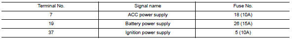
Are the fuses blown? Yes >> replace the blown fuse after repairing the affected circuit.
No >> go to 2.
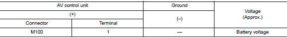
2.Check power supply circuit
- Turn ignition switch OFF.
- Disconnect av control unit connectors m100 and m101.
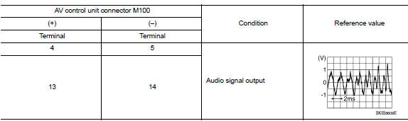
- Check voltage between AV control unit connectors M100 and M101 and ground.
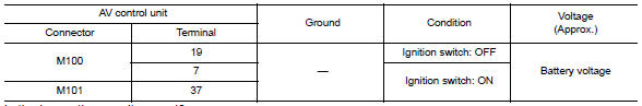
Is the inspection result normal? YES >> GO TO 3.
NO >> Repair or replace harness or connectors.
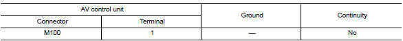
3.Check ground circuit
- Turn ignition switch off.
- Check continuity between av control unit connector m100 and ground.

Is the inspection result normal? Yes >> inspection end.
No >> repair or replace harness or connectors.
Bose speaker amp
Bose speaker amp : diagnosis procedure
Regarding Wiring Diagram information, refer to AV-331, "Wiring Diagram".
1.Check fuse
Check that the following fuses are not blown.
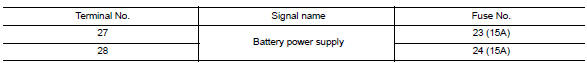
Are the fuses blown? YES >> Replace the blown fuse after repairing the affected circuit.
NO >> GO TO 2.
2.Check power supply circuit
- Turn ignition switch off.
- Disconnect bose speaker amp. Connector b44.
- Check voltage between bose speaker amp. Connector b44 and ground.
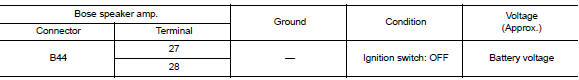
Is the inspection result normal? Yes >> go to 3.
No >> repair or replace harness or connectors.
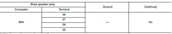
3.Check ground circuit
- Turn ignition switch off.
- Disconnect bose speaker amp. Connector b44.
- Check continuity between Bose speaker amp. connector B44 and ground.
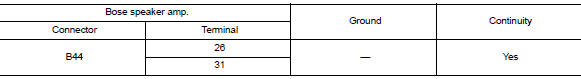
Is the inspection result normal? Yes >> inspection end.
No >> repair or replace harness or connectors.
Front door speaker
Diagnosis procedure
Regarding Wiring Diagram information, refer to AV-331, "Wiring Diagram".
1.Connector check
Check the av control unit, bose speaker amp. And speaker connectors for the following:
- Proper connection
- Damage
- Disconnected or loose terminals
Is the inspection result normal? Yes >> go to 2
No >> repair the terminals or connectors.
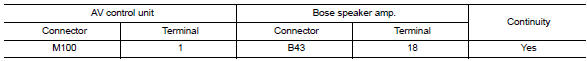
2.Check front door speaker signal circuit continuity (bose speaker amp.)
- Disconnect bose speaker amp. Connector b43 and suspect front door speaker connector.
- Check continuity between bose speaker amp. Connector b43 and suspect front door speaker connector.
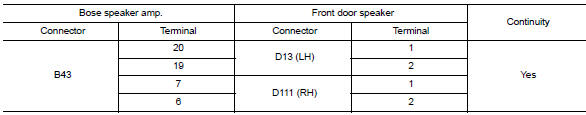
- Check continuity between bose speaker amp. Connector b43 and ground.
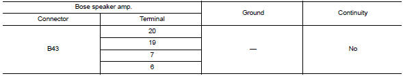
Is the inspection result normal? Yes >> go to 3
No >> repair or replace harness or connectors.
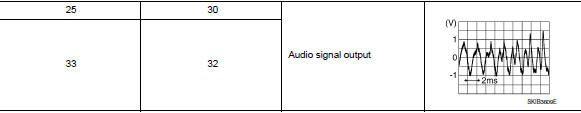
3.Check front door speaker signal (bose speaker amp.)
- Connect bose speaker amp. Connector b43 and suspect front door speaker connector.
- Turn ignition switch to ACC.
- Push AV control unit POWER switch.
- Check signal between the terminals of bose speaker amp. Connector b43.
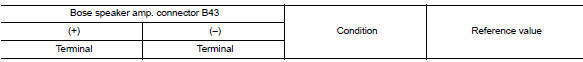
Is the inspection result normal? YES >> Replace front door speaker. Refer to AV-408, "Removal and Installation".
NO >> GO TO 4
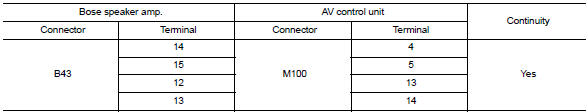
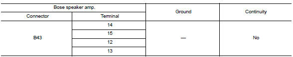
4.Check front door speaker signal circuit continuity (av control unit)
- Turn ignition switch to OFF.
- Disconnect bose speaker amp. Connector b43 and av control unit connector m100.
- Check continuity between bose speaker amp. Connector b43 and av control unit connector m100.
- Check continuity between bose speaker amp. Connector b43 and ground.
Is the inspection result normal? Yes >> go to 5
No >> repair or replace harness or connectors.
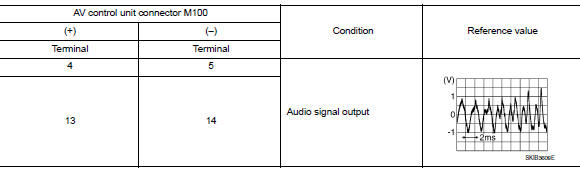
5.Check front door speaker signal (av control unit)
- Connect bose speaker amp. Connector b43 and av control unit connector m100.
- Turn ignition switch to ACC.
- Push av control unit power switch.
- Check signal between av control unit connector m100 and ground.
Is the inspection result normal?
Yes >> replace bose speaker amp. Refer to av-417, "removal and installation".
No >> replace av control unit. Refer to av-406, "removal and installation".
Front tweeter
Diagnosis procedure
Regarding wiring diagram information, refer to av-331, "wiring diagram".
1.Connector check
Check the av control unit, bose speaker amp. And speaker connectors for the following:
- Proper connection
- Damage
- Disconnected or loose terminals
Is the inspection result normal? YES >> GO TO 2
No >> repair the terminals or connectors.
2.Check front speaker signal circuit continuity (bose speaker amp.)
- Disconnect bose speaker amp. Connector b44 and suspect front speaker connector.
- Check continuity between bose speaker amp. Connector b44 and suspect front speaker connector.
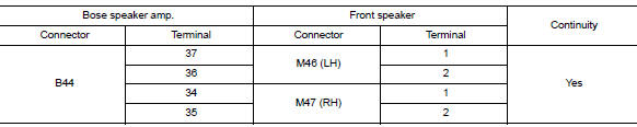
- Check continuity between bose speaker amp. Connector b44 and ground.
Is the inspection result normal? Yes >> go to 3
No >> repair or replace harness or connectors.
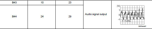
3.Check front speaker signal (bose speaker amp.)
- Connect bose speaker amp. Connector b44 and suspect front speaker connector.
- Turn ignition switch to ACC.
- Push av control unit power switch.
- Check signal between the terminals of bose speaker amp. Connector b44.
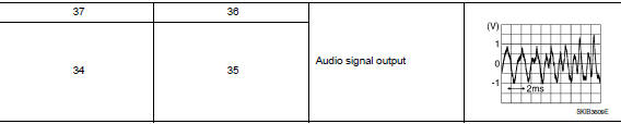
Is the inspection result normal? Yes >> replace front tweeter. Refer to av-407, "removal and installation".
No >> go to 4
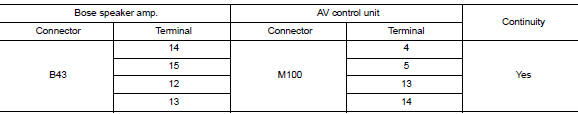
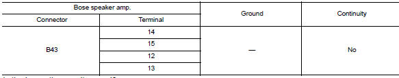
4.Check front speaker signal circuit continuity (av control unit)
- Turn ignition switch to OFF.
- Disconnect Bose speaker amp. connector B43 and AV control unit connector M100.
- Check continuity between Bose speaker amp. connector B43 and AV control unit connector M100.
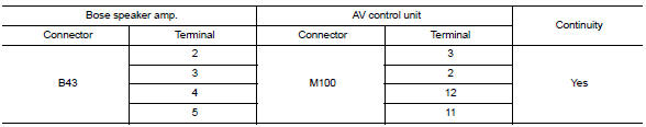
- Check continuity between bose speaker amp. Connector b43 and ground.
Is the inspection result normal? Yes >> go to 5
NO >> Repair or replace harness or connectors.
5.Check front speaker signal (av control unit)
- Connect bose speaker amp. Connector b43 and av control unit connector m100.
- Turn ignition switch to ACC.
- Push av control unit power switch.
- Check signal between av control unit connector m100 and ground.
Is the inspection result normal?
YES >> Replace Bose speaker amp. Refer to AV-417, "Removal and Installation".
NO >> Replace AV control unit. Refer to AV-406, "Removal and Installation".
Rear door speaker
Diagnosis procedure
Regarding wiring diagram information, refer to av-331, "wiring diagram".
1.Connector check
Check the AV control unit, Bose speaker amp. and speaker connectors for the following:
- Proper connection
- Damage
- Disconnected or loose terminals
Is the inspection result normal? Yes >> go to 2
No >> repair the terminals or connectors.
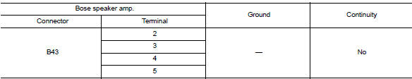
2.Check rear door speaker signal circuit continuity (bose speaker amp.)
- Disconnect Bose speaker amp. connectors and suspect rear door speaker connector.
- Check continuity between bose speaker amp. Connectors and suspect rear door speaker connector.
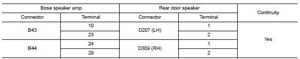
- Check continuity between Bose speaker amp. connectors and ground.
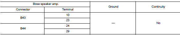
Is the inspection result normal? Yes >> go to 3
NO >> Repair or replace harness or connectors.
3.Check rear door speaker signal (bose speaker amp.)
- Connect Bose speaker amp. connectors and suspect rear door speaker connector.
- Turn ignition switch to acc.
- Push av control unit power switch.
- Check signal between terminals of Bose speaker amp. connectors.
Is the inspection result normal? Yes >> replace rear door speaker. Refer to av-409, "removal and installation".
No >> go to 4
4.Check rear door speaker signal circuit continuity (av control unit)
- Turn ignition switch to OFF.
- Disconnect bose speaker amp. Connector b43 and av control unit connector m100.
- Check continuity between bose speaker amp. Connector b43 and av control unit connector m100.
- Check continuity between bose speaker amp. Connector b43 and ground.
Is the inspection result normal? Yes >> go to 5
No >> repair or replace harness or connectors.
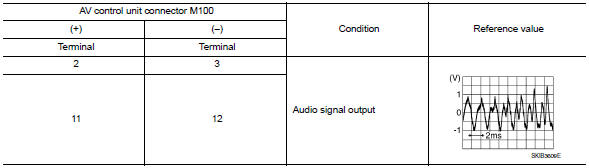
5.Check rear door speaker signal (av control unit)
- Connect bose speaker amp. Connector b43 and av control unit connector m100.
- Turn ignition switch to acc.
- Push av control unit power switch.
- Check signal between AV control unit connector M100 and ground.
Is the inspection result normal?
YES >> Replace Bose speaker amp. Refer to AV-417, "Removal and Installation".
NO >> Replace AV control unit. Refer to AV-406, "Removal and Installation".
Rear woofer
Diagnosis procedure
Regarding wiring diagram information, refer to av-331, "wiring diagram".
1.Connector check
Check the av control unit, bose speaker amp. And speaker connectors for the following:
- Proper connection
- Damage
- Disconnected or loose terminals
Is the inspection result normal? Yes >> go to 2
No >> repair the terminals or connectors.
2.Check rear woofer signal circuit continuity (bose speaker amp.)
- Disconnect Bose speaker amp. connector B44 and suspect rear woofer connector.
- Check continuity between bose speaker amp. Connector b44 and suspect rear woofer connector.
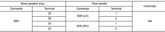
- Check continuity between bose speaker amp. Connector b44 and ground.
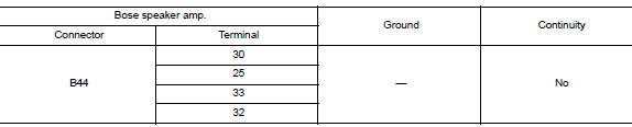
Is the inspection result normal? Yes >> go to 3
No >> repair or replace harness or connectors.
3.Check rear woofer signal (bose speaker amp.)
- Connect bose speaker amp. Connector b44 and suspect rear woofer connector.
- Turn ignition switch to acc.
- Push av control unit power switch.
- Check signal between terminals of Bose speaker amp. connector B44.
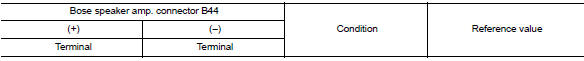
Is the inspection result normal? Yes >> replace rear woofer. Refer to av-410, "removal and installation".
No >> go to 4
4.Check rear woofer signal circuit continuity (av control unit)
- Turn ignition switch to OFF.
- Disconnect Bose speaker amp. connector B43 and AV control unit connector M100.
- Check continuity between Bose speaker amp. connector B43 and AV control unit connector M100.
- Check continuity between Bose speaker amp. connector B43 and ground.
Is the inspection result normal? YES >> GO TO 5
NO >> Repair or replace harness or connectors.
5.Check rear woofer signal (av control unit)
- Connect Bose speaker amp. connector B43 and AV control unit connector M100.
- Turn ignition switch to ACC.
- Push AV control unit POWER switch.
- Check signal between AV control unit connector M100 and ground.
Is the inspection result normal?
YES >> Replace Bose speaker amp. Refer to AV-417, "Removal and Installation".
NO >> Replace AV control unit. Refer to AV-406, "Removal and Installation".
Amp on signal circuit
Diagnosis Procedure
Regarding wiring diagram information, refer to av-331, "wiring diagram".
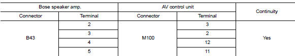
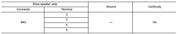
1.Check continuity between av control unit and bose speaker amp.
- Turn ignition switch off.
- Disconnect av control unit connector m100 and bose speaker amp. Connector b43.
- Check continuity between AV control unit connector M100 and Bose speaker amp. connector B43.
- Check continuity between av control unit connector m100 and ground.
Is the inspection result normal? YES >> GO TO 2.
NO >> Repair or replace harness or connectors.
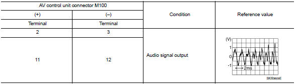
2.Check av control unit voltage
- Connect av control unit connector m100.
- Turn ignition switch ON.
- Check voltage between av control unit connector m100 and ground.
Is the inspection result normal? Yes >> replace bose speaker amp. Refer to av-417, "removal and installation".
No >> replace av control unit. Refer to av-406, "removal and installation".
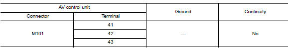
Rear view camera image signal circuit
Diagnosis procedure
Regarding wiring diagram information, refer to av-331, "wiring diagram".
1.Check reverse input signal
- Turn ignition switch on.
- Shift the selector lever to r (reverse).
- Check voltage between AV control unit connector M101 and ground.
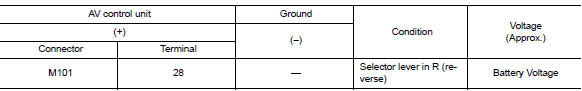
Is inspection result normal? Yes >> go to 2.
No >> repair or replace harness or connectors.
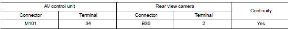
2.Check camera power supply circuit continuity
- Turn ignition switch OFF.
- Disconnect AV control unit connector M101 and rear view camera connector.
- Check continuity between av control unit connector m101 and rear view camera connector b30.
- Check continuity between av control unit connector m101 and ground.
Is inspection result normal? Yes >> go to 3.
No >> repair or replace harness or connectors.
3.Check camera power supply voltage
- Connect AV control unit connector M101 and rear view camera connector.
- Turn ignition switch on.
- Shift the selector lever to R (reverse).
- Check voltage between av control unit connector m101 and ground.
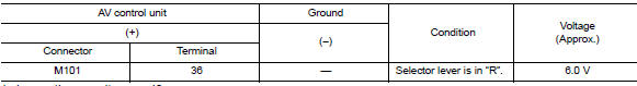
Is inspection result normal? Yes >> go to 4.
No >> replace av control unit. Refer to av-406, "removal and installation".
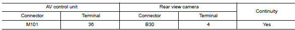
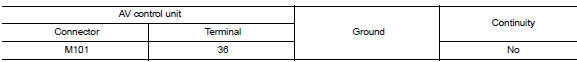
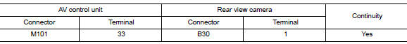
4.Check camera image signal circuit continuity
- Turn ignition switch OFF.
- Disconnect av control unit connector m101 and rear view camera connector.
- Check continuity between AV control unit connector M101 and rear view camera connector B30.
- Check continuity between av control unit connector m101 terminal 34 and ground.
Is inspection result normal? YES >> GO TO 5.
NO >> Repair or replace harness or connectors.
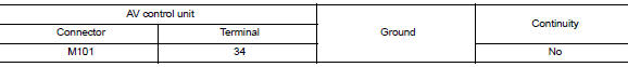
5.Check camera ground circuit continuity
Check continuity between av control unit connector m101 and rear view camera connector b30.
Is inspection result normal? Yes >> go to 6.
No >> repair or replace harness or connectors.
6.Check camera image signal
- Connect av control unit connector m101 and rear view camera connector.
- Turn ignition switch on.
- Shift the selector lever to r (reverse).
- Check signal between av control unit connector m101 and ground.
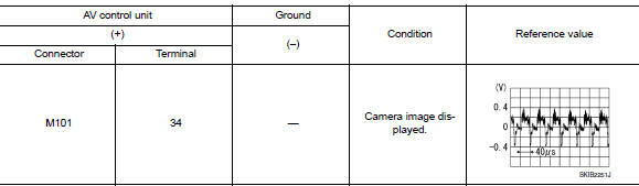
Is inspection result normal? Yes >> replace av control unit. Refer to av-406, "removal and installation".
No >> replace rear view camera. Refer to av-422, "removal and installation".
Microphone signal circuit
Diagnosis procedure
Regarding wiring diagram information, refer to av-331, "wiring diagram".
1.Check microphone signal circuit continuity
- Turn ignition switch off.
- Disconnect av control unit connector m101 and microphone connector r4.
- Check continuity between av control unit connector m101 and microphone connector r4.
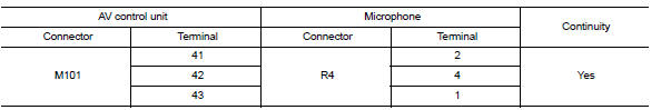
- Check continuity between AV control unit connector M101 and ground.
Is inspection result normal? YES >> GO TO 2.
NO >> Repair or replace harness or connectors.
2.Check microphone vcc voltage
- Connect AV control unit connector M101.
- Turn ignition switch on.
- Check voltage between terminals of av control unit connector m101.
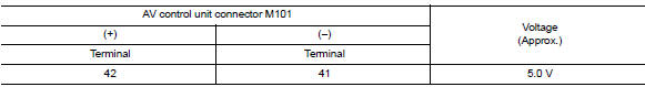
Is the inspection result normal? Yes >> go to 3.
No >> replace av control unit. Refer to av-406, "removal and installation".
3.Check microphone signal
- Connect microphone connector.
- Check signal between terminals of AV control unit connector M101.
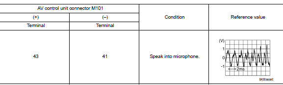
Is the inspection result normal? Yes >> replace av control unit. Refer to av-406, "removal and installation".
No >> replace microphone. Refer to av-421, "removal and installation".
Steering switch
Diagnosis procedure
Regarding wiring diagram information, refer to av-331, "wiring diagram".
1.Check steering wheel audio control switch resistance
- Turn ignition switch OFF.
- Disconnect combination switch (spiral cable) connector M79.
- Check resistance between the terminals of combination switch (spiral cable) connector m79.
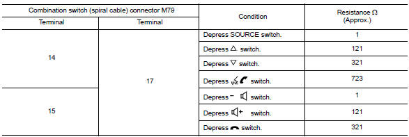
Is the inspection result normal? Yes >> go to 2.
No >> replace steering switches. Refer to av-411, "removal and installation".
2.Check combination switch (spiral cable)
Check continuity between combination switch (spiral cable) connectors m79 and m80.
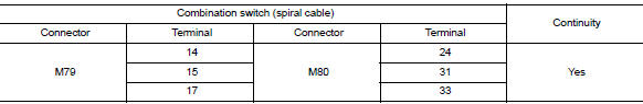
Is the inspection result normal? YES >> GO TO 3.
NO >> Replace combination switch (spiral cable). Refer to SR-16, "Removal and Installation".
3.Check harness between combination switch (spiral cable) and av control uint
- Disconnect AV control unit connector M100.
- Check continuity between combination switch (spiral cable) connector M80 and AV control unit connector M100.
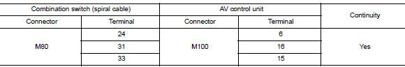
- Check continuity between combination switch (spiral cable) connector m80 and ground.
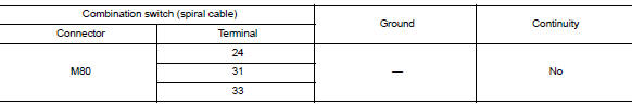
Is the inspection result normal? Yes >> replace av control unit. Refer to av-406, "removal and installation".
No >> repair or replace harness or connectors.
Usb connector
Diagnosis procedure
Regarding wiring diagram information, refer to av-331, "wiring diagram".
1.Check usb interface harness continuity
- Turn ignition switch off.
- Disconnect AV control unit connector M114 and USB interface connector M132.
- Check continuity between av control unit connector m114 and usb interface connector m132.
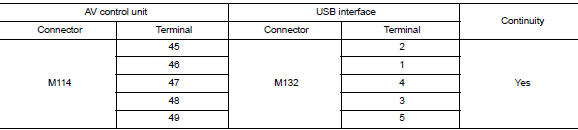
- Check continuity between av control unit connector m131 and ground.
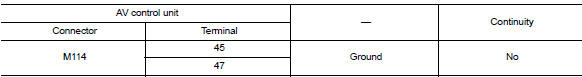
Is the inspection result normal? YES >> Replace the USB interface. Refer to AV-416, "Removal and Installation".
NO >> Repair or replace harness or connectors.
Auxiliary input jack
Diagnosis procedure
Regarding wiring diagram information, refer to av-331, "wiring diagram".
1.Check aux jack harness continuity
- Turn ignition switch off.
- Disconnect av control uint connector m101 and aux jack connector m133.
- Check continuity between av control uint connector m101 and aux jack connector m133.
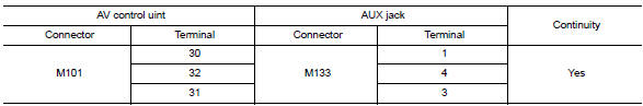
- Check continuity between av control uint connector m101 and ground.
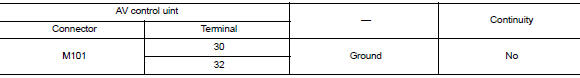
Is the inspection result normal? Yes >> replace the aux jack. Refer to av-416, "removal and installation".
No >> repair or replace harness or connectors.
 Dtc/circuit diagnosis
U1000 can comm circuit
DTC Logic
Dtc detection logic
Consult display
Dtc detection condition
Possible cause
Can comm circuit
[u1000]
Av control unit is not transmitting ...
 Symptom diagnosis
Multi av system
Symptom table
Related to audio
Related to hands-free phone
Before performing diagnosis, confirm that the cellular phone being used
by the customer is compatible w ...
Other materials:
Oil filter
Removal and Installation
REMOVAL
Remove engine under cover. Refer to EXT-16, "Exploded View".
Drain engine oil. Refer to LU-8, "Draining".
Remove the oil filter using Tool (A) as shown.
: Front
Tool number : KV10115801 (J-38956)
WARNING:
Be careful not to burn you ...
Cooler pipe and hose
Exploded view
High-pressure service port
High-pressure pipe
Expansion valve
Low-pressure service port
Low-pressure flexible hose
Compressor
Refrigerant pressure sensor
Condenser and liquid tank assembly
High-pressure flexible hose
Low-pressure flexible hose
Low-pressure f ...
Front door
Door assembly
Door assembly : removal and installation
CAUTION:
Use two people when removing or installing the front door assembly
due to its heavy weight.
When removing and installing front door assembly, support front
door using a suitable tool.
Do not use air tools or electric to ...
