Nissan Sentra Service Manual: Basic inspection
Diagnosis and repair work flow
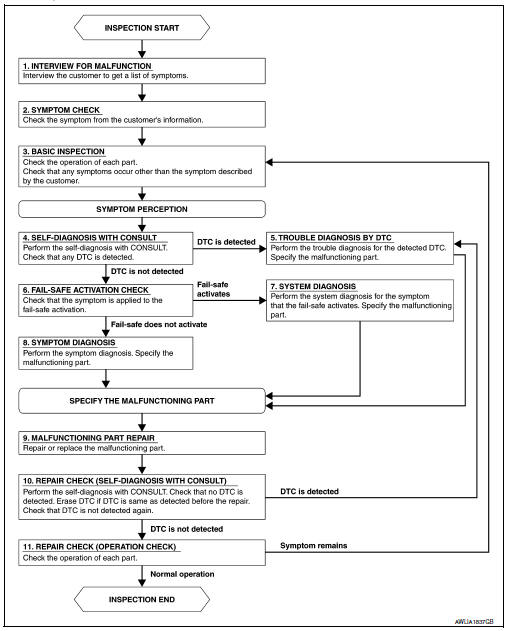
Work flow
OVERALL SEQUENCE
DETAILED FLOW
1.INTERVIEW FOR MALFUNCTION
Find out what the customer's concerns are.
>> GO TO 2
2.SYMPTOM CHECK
Verify the symptom from the customer's information.
>> GO TO 3
3.BASIC INSPECTION
Check the operation of each part. Check that any concerns occur other than those mentioned in the customer interview.
>> GO TO 4
4.SELF-DIAGNOSIS WITH CONSULT
Perform the self diagnosis with CONSULT. Check that any DTC is detected.
Is any DTC detected? YES >> GO TO 5
NO >> GO TO 6
5.TROUBLE DIAGNOSIS BY DTC
Perform the trouble diagnosis for the detected DTC. Specify the malfunctioning part.
>> GO TO 9
6.FAIL-SAFE ACTIVATION CHECK
Determine if the customer's concern is related to fail-safe activation.
Does the fail-safe activate? YES >> GO TO 7
NO >> GO TO 8
7.SYSTEM DIAGNOSIS
Perform the system diagnosis for the system in which the fail-safe activates. Specify the malfunctioning part.
>> GO TO 9
8.SYMPTOM DIAGNOSIS
Perform the symptom diagnosis. Specify the malfunctioning part.
>> GO TO 9
9.MALFUNCTION PART REPAIR
Repair or replace the malfunctioning part.
>> GO TO 10
10.REPAIR CHECK (SELF-DIAGNOSIS WITH CONSULT)
Perform the self diagnosis with CONSULT. Verify that no DTCs are detected. Erase all DTCs detected prior to the repair. Verify that DTC is not detected again.
Is any DTC detected? YES >> GO TO 5
NO >> GO TO 11
11.REPAIR CHECK (OPERATION CHECK)
Check the operation of each part.
Does it operate normally?
YES >> Inspection End.
NO >> GO TO 3
 Wiring diagram
Headlamp
Wiring diagram
Daytime light system
Wiring diagram
Auto light system
Wiring diagram
Front fog lamp
Wiring diagram
...

Other materials:
Steering knuckle
Exploded View
Steering knuckle
Splash guard
Wheel stud
Wheel hub and bearing
Disc brake rotor
Wheel hub lock nut
Nut retainer
Cotter pin
Removal and Installation
REMOVAL
Remove the wheel and tire using power tool. Refer to WT-47, "Exploded
View".
Remove ...
Service data and specifications
(sds)
Periodical Maintenance Specification
ENGINE COOLANT CAPACITY (APPROXIMATE)
Radiator
Thermostat
Water Control Valve
...
Diagnosis system (combination meter)
Description
COMBINATION METER SELF-DIAGNOSIS MODE
The information display, speedometer and tachometer can be checked in
self-diagnosis mode.
STARTING COMBINATION METER SELF-DIAGNOSIS MODE
NOTE:
Check combination meter power supply and ground circuits if
self-diagnosis mode does not star ...
