Nissan Sentra Service Manual: Strg branch line circuit
Diagnosis procedure
1.Check connector
- Turn the ignition switch off.
- Disconnect the battery cable from the negative terminal.
- Check the terminals and connectors of the steering angle sensor for damage, bend and loose connection (unit side and connector side).
Is the inspection result normal? YES >> GO TO 2.
NO >> Repair the terminal and connector.
2.Check harness for open circuit
- Disconnect the connector of steering angle sensor.
- Check the resistance between the steering angle sensor harness connector terminals.
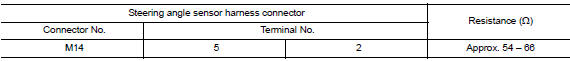
Is the measurement value within the specification? Yes >> go to 3.
No >> repair the steering angle sensor branch line.
3.Check power supply and ground circuit
Check the power supply and the ground circuit of the steering angle sensor. Refer to BRC-44, "Wiring Diagram".
Is the inspection result normal? YES (Present error)>>Replace the steering angle sensor. Refer to BRC-113, "Removal and Installation".
YES (Past error)>>Error was detected in the steering angle sensor branch line.
NO >> Repair the power supply and the ground circuit.
 M&A branch line circuit
Diagnosis procedure
1.Check connector
Turn the ignition switch off.
Disconnect the battery cable from the negative terminal.
Check the terminals and connectors of the combination meter for da ...
 Hvac branch line circuit
Diagnosis procedure
1.Check connector
Turn the ignition switch OFF.
Disconnect the battery cable from the negative terminal
Check the terminals and connectors of the a/c auto amp. For damage, ...
Other materials:
Optical sensor
Description
The optical sensor measures ambient light and transmits the optical sensor
signal to the bcm.
Component function check
1.Check optical sensor signal by consult
Consult
Turn the ignition switch ON.
Select opti sen of bcm (head lamp) data monitor item.
Turn the lighting swit ...
Basic inspection
Diagnosis and repair work flow
Work Flow
Overall sequence
Detailed flow
1. Get information for symptom
Get the detailed information from the customer about the symptom (the
condition and the environment when
the incident/malfunction occurred).
>> Go to 2.
2. Check dtc
Check ...
How to Follow Test Groups in Trouble Diagnosis
Test group number and test group title
Test group number and test group title are shown in the upper portion of
each test group.
Work and diagnosis procedure
Start to diagnose a problem using procedures indicated in enclosed test
groups.
Questions and results
...
