Nissan Sentra B18 (2020-2025) Service Manual: Steering System :: Unit Disassembly and Assembly. Steering Gear and Linkage
Steering Gear and Linkage. Exploded View
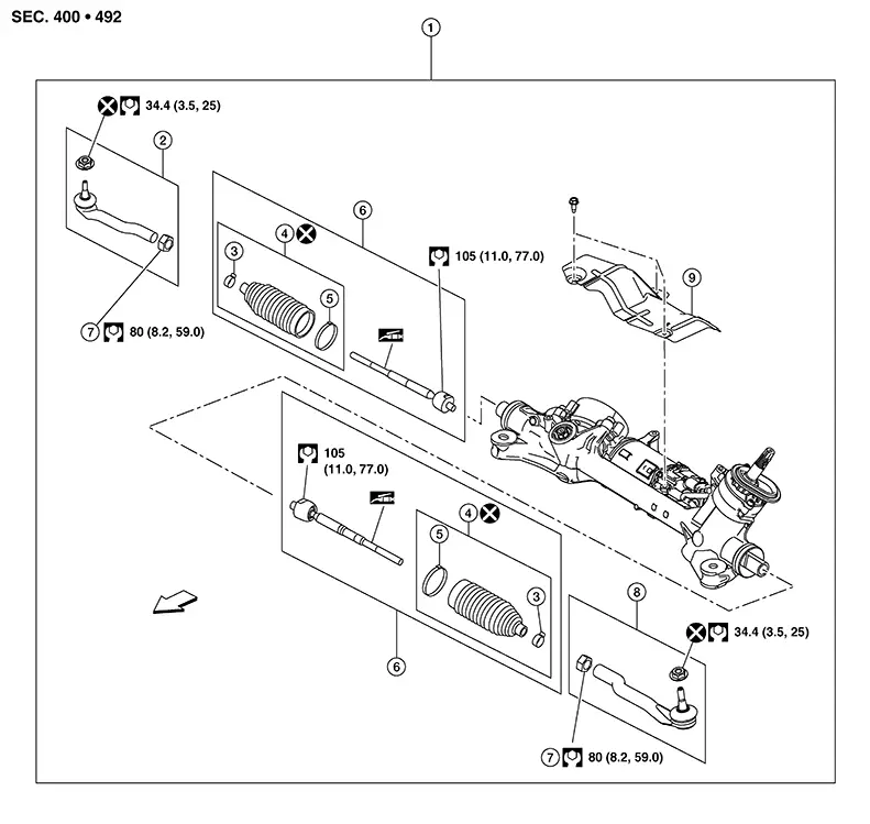
Exploded View
|
1. |
Steering gear and linkage assembly |
2. |
Outer socket (RH) |
3. |
Small boot clamp |
|
4. |
Boot kit |
5. |
Large boot clamp |
6. |
Inner socket kit |
|
7. |
Lock nut |
8. |
Outer socket (LH) |
|
Front |
Disassembly and Assembly
Disassembly and Assembly
DISASSEMBLY
Loosen
inner socket lock nut (A) and remove outer socket (1). 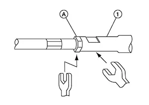
CAUTION:
To prevent damage, hold outer socket (1) across flats using suitable tool while loosening inner socket lock nut (A).
Remove boot clamps and boot.
CAUTION:
Do not reuse boot clamps or boot.
Remove inner socket.
ASSEMBLY
Apply medium strength thread locker to threads of inner socket. Install inner socket and tighten to specified torque. Refer to Exploded View.
Install
large end of boot (1) to steering gear housing. 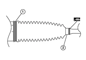
CAUTION:
Do not reuse boot.
Apply silicone grease between inner socket and small end of boot.
CAUTION:
To prevent boot deformation or damage during toe-in adjustment, apply silicone grease between inner socket and small end of boot.
Install small end of boot (2) to inner socket boot mounting groove.
Install
small boot clamp (B). 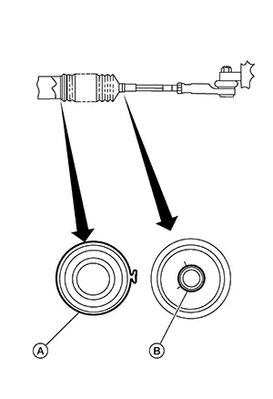
CAUTION:
Do not reuse boot clamps.
Install large boot clamp (A).
CAUTION:
Do not reuse boot clamps.
Install inner socket lock nut and outer socket.
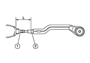
Adjust inner socket (1) to standard length (L), then tighten inner socket lock nut (2) to specification. Refer to Exploded View. Verify inner socket length after tightening lock nut.
|
Inner socket length (L) |
: Refer to Inner Socket Length. |
CAUTION:
To prevent damage, hold outer socket across flats using suitable tool while tightening inner socket lock nut.
Other materials:
Front Bumper
Exploded View
Exploded View
1.
Front bumper side bracket (RH)
2.
Front bumper reinforcement support
(RH)
...
Power Supply and Ground Circuit (ecm)
Diagnosis Procedure
Diagnosis Procedure
CHECK THE BATTERY CABLE
Turn ignition switch OFF.
Check the battery cable for tightening
enough.
Note:
Check the continuity between the
battery ...
B203d-14 Inside Antenna
Dtc Description
DTC Description
DTC DETECTION LOGIC
DTC No.
CONSULT screen items
(Trouble diagnosis content)
DTC detecting condition
...