Nissan Sentra B18 (2020-2025) Service Manual: Steering System :: Removal and Installation
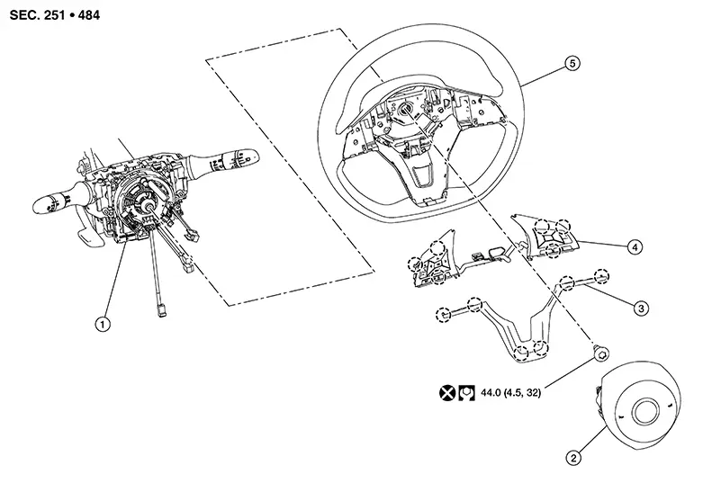
Steering Wheel. Exploded View
Exploded View
|
1. |
Steering column assembly |
2. |
Driver air bag module |
3. |
Finisher |
|
4. |
Steering switches |
5. |
Steering wheel |
|
Pawl |

Removal and Installation
Removal and Installation
REMOVAL
Set the front wheels and tires to the straight-ahead position.
Remove driver air bag module. Refer to Removal and Installation.
Disconnect steering switches harness connector from spiral cable.
Remove steering wheel bolt.
CAUTION:
Do not reuse bolt.
Remove steering wheel using suitable tool.
CAUTION:
Place a piece of tape across spiral cable so it will not be rotated out of position.
Inspect steering wheel near puller holes for damage. If damaged, replace steering wheel.
Remove the following parts from the steering wheel (if necessary):
-
Steering switches
-
Finisher
INSTALLATION
-
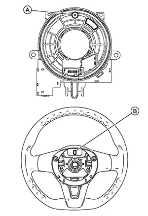
Align spiral cable correctly before installing steering wheel. Make sure that spiral cable is in neutral position ending up with locating pin (A) on top.
-
During steering wheel installation, make sure spiral cable locating pin (A) is aligned with slot (B) on back of steering wheel.
CAUTION:
If cable is not installed in correct position, spiral cable may snap by turning steering wheel beyond limited number of turns.
-
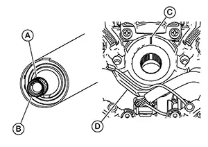
Align center mark (A) on steering column shaft (B) with center mark (C) on steering wheel hub (D).
-
Installation of remaining components is in the reverse order of removal.
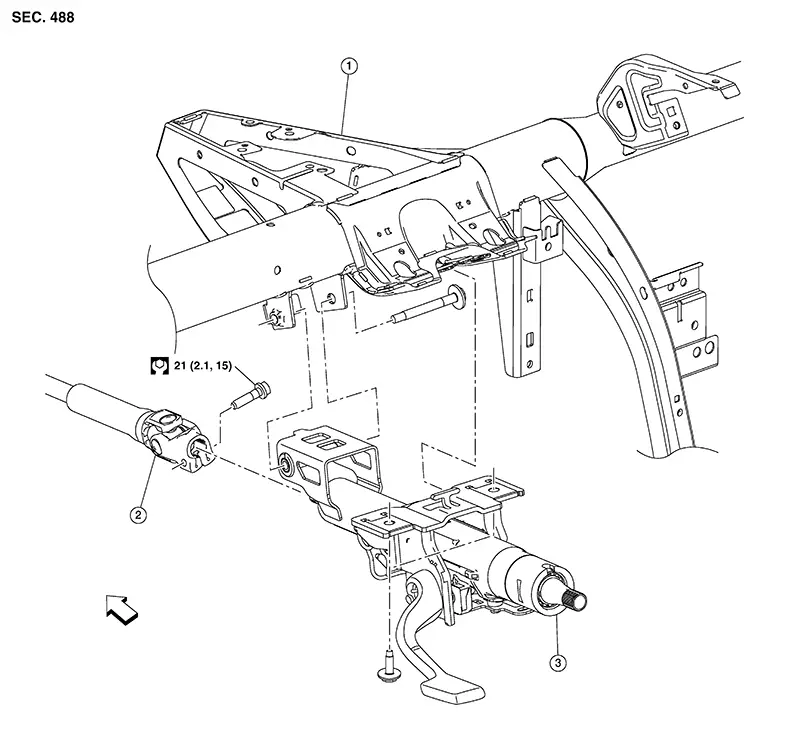
Steering Column. Exploded View
Exploded View
|
1. |
Steering member |
2. |
Lower joint |
3. |
Steering column |
|
|
Front |

Removal and Installation
Removal and Installation
REMOVAL
CAUTION:
-
Do not cause impact to steering column during removal and installation.
-
Do not move steering gear during removal and installation of steering column.
Set the front wheels and tires to the straight-ahead position.
Remove instrument lower panel LH. Refer to Removal and Installation.
Remove combination switch. Refer to Removal and Installation (Type A) or Removal and Installation (Type B).
Release
harness retainer clips (A) and separate harness from steering
column (1). 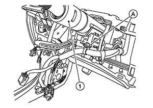
Remove bolt
(A) and separate lower joint (2) from steering column (1). 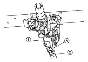
CAUTION:
Place a matching mark on both lower joint and steering column before separating.
Remove
bolts (A). 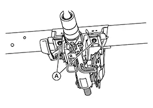
Remove bolt
(A). 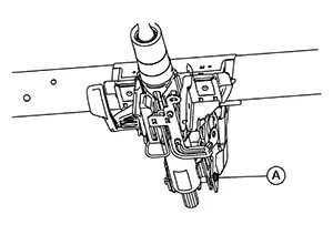
Disengage
tab (A) from steering member and remove steering column from
Nissan Sentra vehicle. 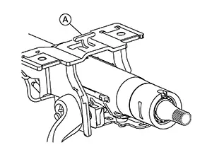
INSPECTION AFTER REMOVAL
-
Check each part of steering column for damage or wear. If damage is found, replace steering column.
-
If Nissan Sentra vehicle has been involved in a collision, or if noise and rattles are heard during a turn, check the length of the steering column. Refer to Inspection. If steering column length is out of specification, replace steering column.
INSTALLATION
CAUTION:
Do not apply undue stress to steering column.
Align lower
joint (2) and steering column matching mark and install steering
column (1) to lower joint. 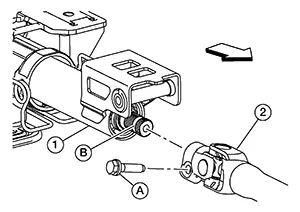
|
|
Front |
Install bolt (A) finger-tight. Verify bolt (A) is seated in groove (B) and tighten to specification. Refer to Exploded View.
CAUTION:
Bolt is (A) directional. Refer to Exploded View.
Installation of remaining components is in the reverse order of removal.
CAUTION:
-
Install steering column bolts finger-tight, then tighten to specification.
-
Tighten steering column bolts to specification in the sequence shown:

Sequence number
Torque
No. 1
: 20.15 N·m (2.1 kg-m, 15 ft-lb)
No. 2 and No. 3
: 16.7 N·m (1.7 kg-m, 12 ft-lb)
-
Check tilt and telescope mechanism operating range. Refer to Inspection.
-
Verify steering column tab (A) is centered to steering member slot (B).
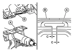
C:
1.0 mm
INSPECTION AFTER INSTALLATION
CAUTION:
Verify steering column length after installation. Refer to Inspection.
-
Turn steering wheel to make sure it moves smoothly while turning to left and right stops.
-
Make sure the number of turns are the same from the straight-forward position to left and right stops.
-
Make sure that steering wheel is in neutral position when driving straight ahead.
-
Adjust neutral position of steering angle sensor. Refer to Description.
Lower Joint. Exploded View
Exploded View
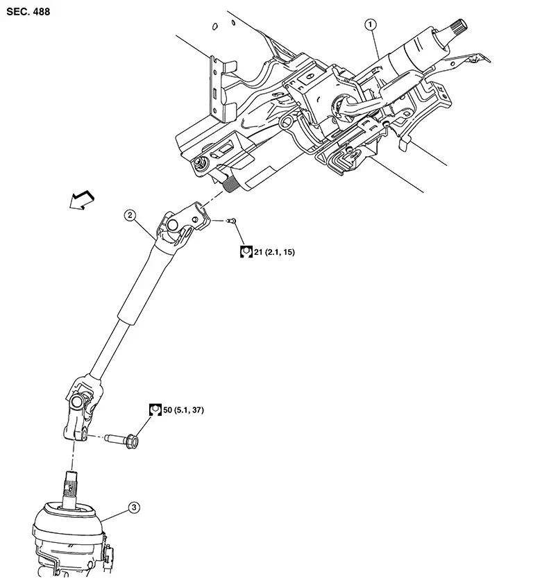
|
1. |
Steering column |
2. |
Lower joint |
3. |
Steering gear |
|
|
Front |
Removal and Installation
Removal and Installation
CAUTION:
-
Do not cause impact to the steering column during lower joint removal and installation.
-
Do not move the steering gear during removal and installation of the lower joint.
REMOVAL
Set the front wheels and tires to the straight-ahead position.
CAUTION:
Secure the steering wheel with string so that it will not be rotated out of position and damage the spiral cable.
Place tilt to the highest level.
CAUTION:
Securely lock the tilt lever.
Remove the instrument lower panel LH. Refer to Removal and Installation.
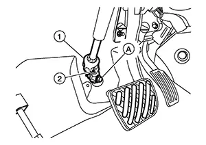
Remove bolt
(A) and separate lower joint (1) from steering gear pinion shaft
(2). 
Remove bolt
(A), separate lower joint (2) from steering column (1), and remove
lower joint. 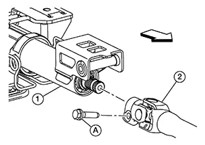
|
|
Front |
CAUTION:
Place a matching mark on both lower joint and steering column before separating.
INSTALLATION
Align lower joint to steering column matching mark and install to steering column.
Install
bolt (A) to lower joint (2) finger-tight. Verify bolt is seated in
steering column (1) pinion shaft groove (B).
|
|
Front |
CAUTION:
Bolt (A) is directional. Refer to Exploded View.
Align lower
joint (1) bolt hole (A) with steering gear pinion shaft (2) groove
(B). 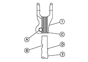
Connect lower joint to steering gear pinion shaft until surface (C) contacts surface (D).
Install lower joint bolt finger-tight.
CAUTION:
Lower joint bolt is directional. Refer to Exploded View.
Tighten all lower joint bolts to specification. Refer to Exploded View.
CAUTION:
-
Make sure steering wheel is in neutral position when driving straight ahead.
-
Adjust neutral position of steering angle sensor. Refer to Description.
INSPECTION AFTER INSTALLATION
CAUTION:
Verify lower joint length after installation. Refer to Lower Joint.
-
Turn steering wheel to make sure it moves smoothly while turning to left and right stops.
-
Make sure number of turns are the same from straight-forward position to left and right stops.
Steering Gear and Linkage. Exploded View
Exploded View
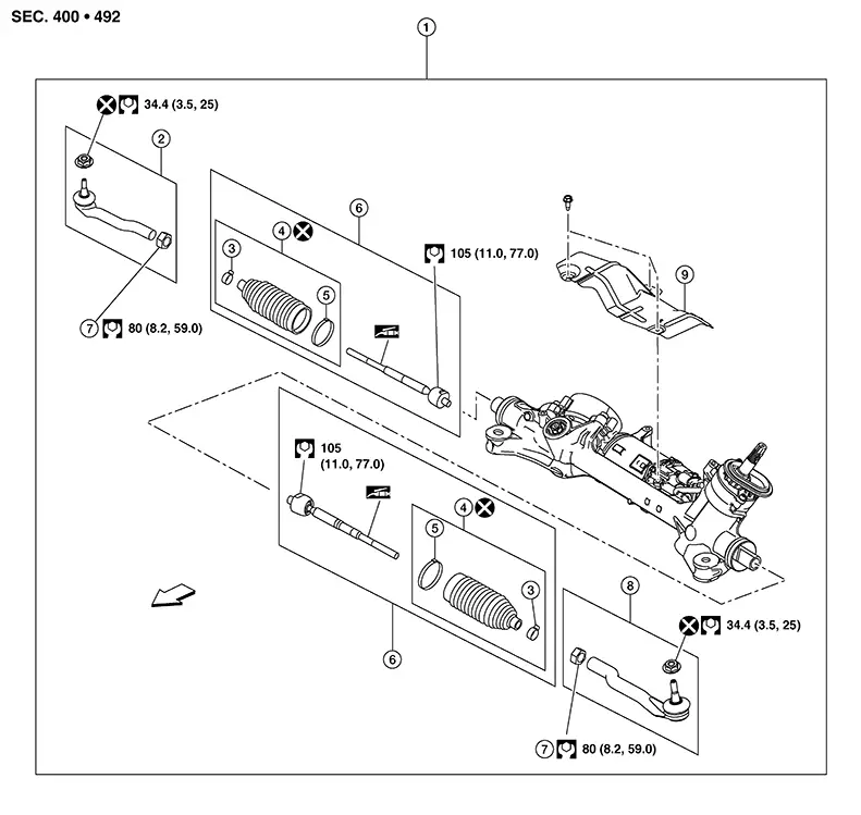
|
1. |
Steering gear and linkage assembly |
2. |
Outer socket (RH) |
3. |
Small boot clamp |
|
4. |
Boot kit |
5. |
Large boot clamp |
6. |
Inner socket kit |
|
7. |
Lock nut |
8. |
Outer socket (LH) |
9. |
Heat shield |
|
|
Front |
Removal and Installation - Outer Socket
Removal and Installation - Outer socket
REMOVAL
Remove front wheel and tire using power tool. Refer to Removal and Installation.
Loosen
inner socket lock nut (A). 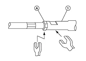
CAUTION:
To prevent damage, hold outer socket (1) across flats using suitable tool while loosening inner socket lock nut (A).
Loosen outer socket nut and separate outer socket from steering knuckle using suitable tool.
CAUTION:
Leave the outer socket nut half threaded on the outer socket to prevent damage to threads and to prevent the suitable tool from coming off suddenly.
Disconnect stabilizer bar connecting rod from stabilizer bar (LH/RH) and rotate stabilizer bar upward to gain clearance.
Remove outer socket nut and outer socket.
CAUTION:
Do not reuse outer socket nut.
INSTALLATION
Install outer socket to inner socket.
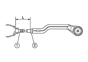
Adjust inner socket (1) to standard length (L), then tighten inner socket lock nut (2) to specification. Refer to Exploded View. Verify inner socket length after tightening lock nut.
|
Inner socket length (L) |
: Refer to Inner Socket Length. |
CAUTION:
-
To prevent damage, hold outer socket across flats using suitable tool while tightening inner socket lock nut.
-
Adjust toe-in after this procedure. The length achieved after toe-in adjustment is not necessarily the above value.
-
Inspect to make sure no boot deformation has occurred during toe-in adjustment. Adjust boot as necessary.
Install outer socket to steering knuckle.
Install outer socket nut to outer socket and tighten to specification. Refer to Exploded View.
CAUTION:
Do not reuse outer socket nut.
Connect stabilizer bar connecting rod (LH/RH).
Install front wheel and tire. Refer to Removal and Installation.
CAUTION:
-
Check wheel alignment. Refer to Inspection.
-
Adjust the neutral position of the steering angle sensor. Refer to Description.
Removal and Installation - Boot
Removal and Installation - Boot
REMOVAL
Remove outer socket. Refer to Removal and Installation - Outer socket.
Remove inner socket lock nut.
Remove small boot clamp and large boot clamp.
CAUTION:
Do not reuse boot clamps.
Remove boot.
CAUTION:
Do not reuse boot.
INSTALLATION
Install
large end of boot (1) onto steering gear housing.
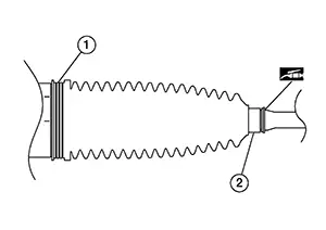
CAUTION:
Do not reuse boot.
Apply silicone grease between the inner socket and small end of boot (2).
CAUTION:
To prevent boot deformation or damage during toe-in adjustment, apply silicone grease between the inner socket and small end of boot.
Install small end of boot to inner socket boot mounting groove.
Install small boot clamp (B).
CAUTION:
Do not reuse small boot clamp.
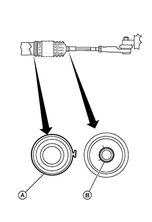
Install large boot clamp (A).
CAUTION:
Do not reuse large boot clamp.
Partially thread the inner socket lock nut on the inner socket.
Install outer socket. Refer to Removal and Installation - Outer socket.
Removal and Installation - Inner Socket
Removal and Installation - Inner socket
REMOVAL
Remove boot. Refer to Removal and Installation - Boot.
Remove inner socket. Refer to Exploded View.
INSTALLATION
Apply medium strength thread locker to threads of inner socket. Install inner socket and tighten to specified torque. Refer to Exploded View.
Install boot. Refer to Removal and Installation - Boot.
Install outer socket. Refer to Removal and Installation — Outer socket.
Other materials:
Bcm (body Control Module)
List of Ecu Reference
List of ECU Reference
ECU
Reference
BCM
Values on the Diagnosis Tool
...
Intake Sensor
Diagnosis Procedure
Diagnosis Procedure
CHECK INTAKE SENSOR
Ignition switch OFF.
Remove intake sensor. Refer to Removal and Installation.
Check resis ...
Sonar System. Ecu Diagnosis Information. Sonar Control Unit
Sonar Control Unit
Values on the Diagnosis Tool
Values on the Diagnosis Tool
Note:
The following table includes information (items)
inapplicable to this Nissan Sentra vehicle. For information (items) applicable to
this vehicle, refer to CONSULT display items.
...