Nissan Sentra B18 (2020-2025) Service Manual: Spiral Cable
Exploded View
Exploded View
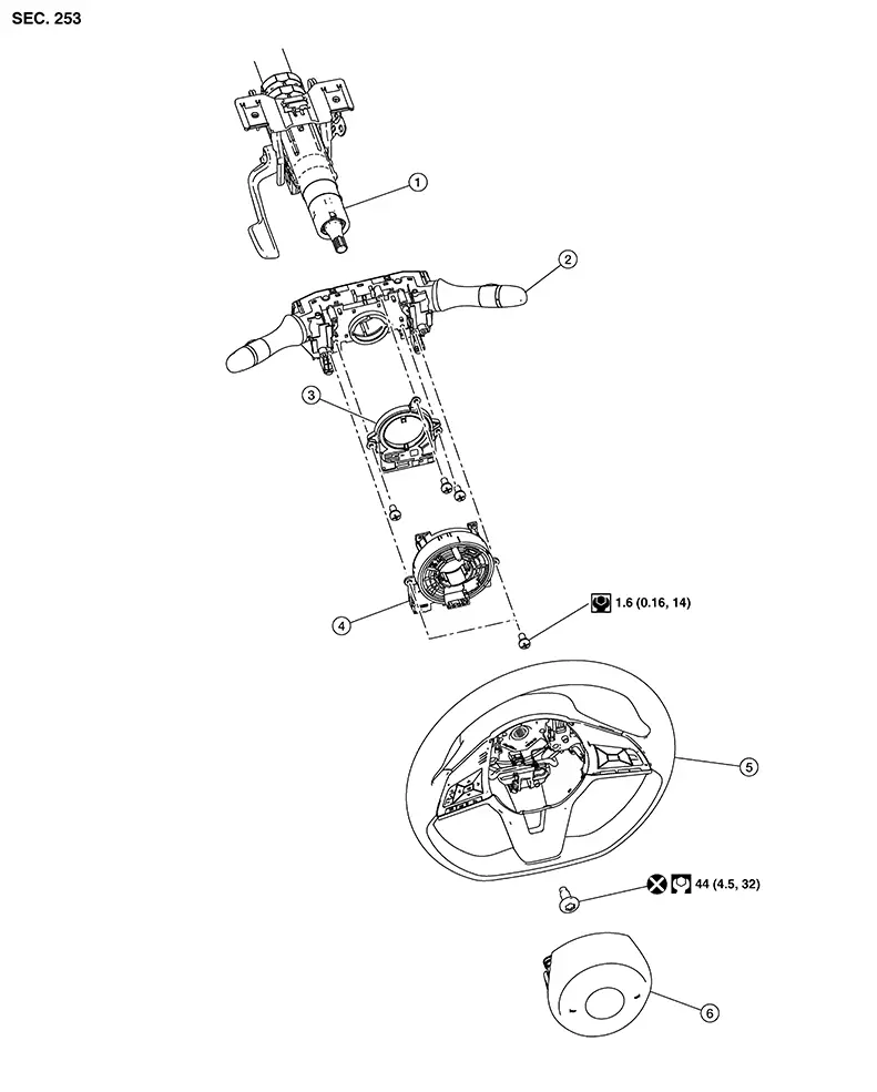
|
1. |
Steering column |
2. |
Combination switch |
3. |
Chassis control module (with built in steering angle sensor) |
| 4. |
Spiral cable |
5. |
Steering wheel |
6. |
Driver air bag module |
Removal and Installation
Removal and Installation
Warning:
-
Before servicing the SRS, place the ignition switch in the OFF position, disconnect both battery terminals then wait at least three minutes.
-
Always work from the side of the driver air bag module. Do not work in front of it.
-
Do not use air tools or electric tools for servicing the driver air bag module.
-
Always place the driver air bag module with the pad side facing upward.
-
Do not cause impact to the driver air bag module by dropping, etc. Replace the driver air bag module if it has been dropped or sustained an impact.
-
Do not allow oil, grease, detergent, or water to come in contact with the driver air bag module.
REMOVAL
Remove the steering wheel. Refer to Removal and Installation.
Remove the steering column upper cover and steering column lower cover. Refer to Removal and Installation.
Disconnect the harness connector from the spiral cable.
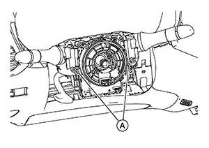
Remove the
screws (A) and remove the spiral cable.
CAUTION:
-
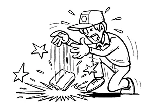
Do not strike or impact the spiral cable.
-
Replace the spiral cable if it has been dropped or sustained an impact.
-
Do not disassemble the spiral cable.
-
Do not apply lubricant to the spiral cable.
-
Do not allow oil, grease, detergent, or water to come in contact with the spiral cable.
INSTALLATION
Installation is in the reverse order of removal.
-
The turn signal lever must be in the neutral position for spiral cable installation.
-
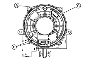
Set the spiral cable neutral position by carefully turning the spiral cable clockwise about 2 and a half turns stopping when the locating pin (A) is at the top most position, the triangles (B) are pointing at each other as shown and the clear window (C) appears yellow.
 Note:
Note: 
-
If a new part is installed, the neutral position is already set with a lock pin in place and should not be adjusted after the stopper clip is removed. Make sure the lock pin is removed after the steering column covers are installed but before the steering wheel is installed.
-
Snap off lock pin (A) from the spiral cable (1) in the direction shown to remove lock pin.
Note:Spiral cable removed for clarity. 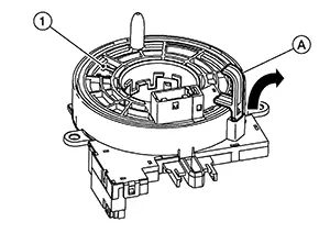
-
-
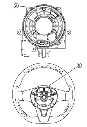
During steering wheel installation, make sure the spiral cable locating pin (A) is aligned with slot (B) on back of steering wheel.
CAUTION:
-
The spiral cable may snap during steering operation if the spiral cable is installed in an improper position.
-
Do not overturn the spiral cable or go beyond the maximum number of turns allowed. This will cause the spiral cable to snap.
-
The turn signal lever must be in the neutral position for spiral cable installation.
-
Do not apply lubricant to the spiral cable.
-
Do not allow oil, grease, detergent or water to come in contact with the spiral cable.
-
After installation is complete, check that no system malfunction is detected causing the air bag warning lamp to illuminate.
-
If a malfunction is indicated by the air bag warning lamp after repair or replacement of the malfunctioning parts, perform the SRS final check. Refer to SRS Final Check.
Other materials:
Bcm
B2c21-23 Front Seat Belt Buckle Switch Lh
Dtc Description
DTC Description
DTC DETECTION LOGIC
DTC No.
CONSULT screen items
(Trouble diagnosis
content)
...
Text messaging
WARNING
Laws in some jurisdictions may restrict the use of Text-to-Speech features.
Always check local regulations before using this function in your Nissan
Sentra.
Laws in some jurisdictions may limit the use of certain applications
and features, including social networking a ...
P1197 Out of Gas
Dtc Description
DTC Description
This diagnosis result is detected when the fuel level of the fuel
tank is extremely low and the engine does not run normally.
DTC DETECTION LOGIC
DTC
...