Nissan Sentra B18 (2020-2025) Service Manual: Sheet Metal Work
Sheet Metal Work Tools
Sheet Metal Work Tools
Sheet Metal Work Tools
This section explains various tools used in body repair work.
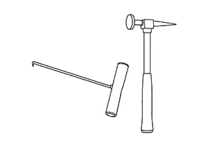
Hammers
Hammers
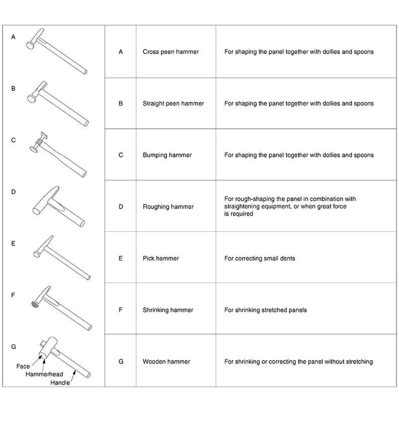
A hammer is used to correct dents, projections or other deformations. Various shapes have been designed according to their purposes.
(1) TYPES AND FEATURES OF HAMMERS
(2) SELECTION AND MAINTENANCE OF HAMMERS
It is necessary to choose lighter or heavier hammers according to application or purpose.
Hammer weight should be selected according to the user's physical strength.
Hammer maintenance is important. In particular, the hammer face must always be kept clean. A distorted or damaged hammer face will lead to distorted panels.
Accordingly, hammers for sheet metal work must not be used to hit other objects such as a chisel. Do not mix sheet metal hammers with ordinary hammers.
Repairing the face of a sheet metal hammer is explained below.
Note:
To avoid damage to the Nissan Sentra vehicle, always use separate hammers on aluminum and steel.
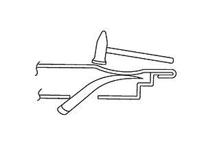
(a) Clamp the hammer in a vise with the hammer face up.

If the hammer face is deformed, use a hand file to smooth it.
(b) File the face in all directions. Do not file in only one direction.
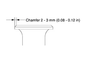
(c) Chamfer the edge of the face to prevent it from nicking or distoring the sheet metal.
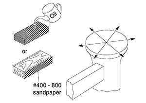
(d) After smoothing the hammer face, polish it with an oil stone or #400 - #800 abrasive paper wrapped around a wooden block. Polish the face in all directions.
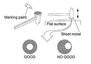
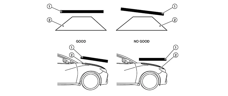
(e) To check the finish, apply marking paint to the hammer face . Hit a piece of flat sheet metal on a flat surface.
|
GOOD |
: The paint comes off the center of the face. |
|
NO GOOD |
: The paint comes off at a section other than the center or the face. Grind the surface again. |
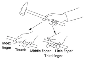
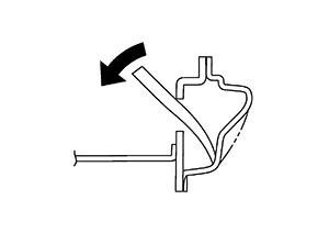
(3) HOLDING AND HITTING WITH THE HAMMER
(a) Holding the hammer
-
Hold the hammer handle tightly with the middle, third and little fingers so that it will not slip when it is swung.
-
Hold the sides of the hammer handle lightly with the thumb and index finger to prevent sideways movement.
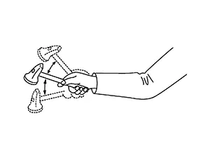
(b) Hammering
-
For rough straightening work, strike strongly.
For ordinary correcting work, swing the hammer using the wrist. In this case, the arm serves as a guide to determine the hammer direction.
-
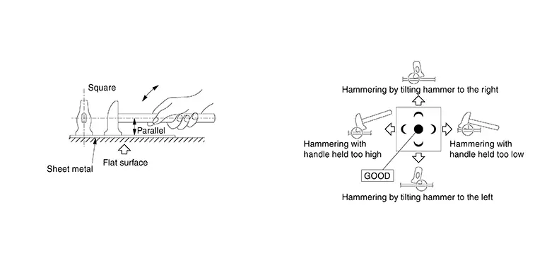
The hammer face should be flush with the panel surface when hitting. If the hammer edge strikes the surface, it will nick the panel.
-
Hammering should be approximately 100 hits a minute, and should be kept constant. An irregular hammering rhythm will lead to an uneven hammering force. Sheet metal will stretch when it is hammered. Irregular hammering also makes sheet metal correction more difficult.
Dollies
Dollies
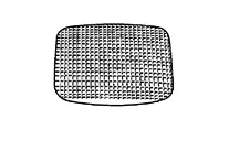
Dollies are used in combination with a hammer. They are a 1 kg - 2 kg (2 lb - 4 lb) steel blocks, heavier than a hammer, with various curves and planes.
(1) USE OF DOLLIES
(a) Place the dolly on the underside of the deformed sheet metal.
Strike the deformed section of the sheet metal with the hammer to stretch it.
(b) Move the hammer and dolly as necessary, and direct the hammer blows so as to bend the sheet metal.
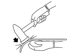
(c) If ordinary hammering is impossible due to limited space, substitute a dolly for the hammer, and strike the dented portion with the dolly.
(2) TYPES AND FEATURES OF DOLLIES
|
General purpose dolly |
This is also called a rail dolly. It has both wide and narrow curved faces. |
|
Utility dolly |
This type of dolly features various curved surfaces and has wide applicability to automobile body repair work. It can be handled easily in narrow spaces. |
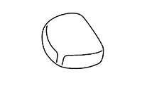
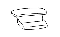
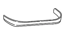
|
Heel dolly |
One side is flat and the other side is curved slightly. This is suitable for correcting flat and slightly curved surfaces. |
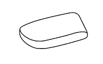
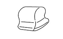
|
Toe dolly |
This dolly is formed by two flat surfaces and a connecting curved surface. It can be used in narrow places. |
|
Round dolly |
Both sides are curved. This dolly is used for repairing small dents. |
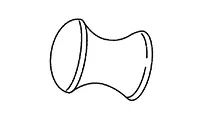
|
Wedge dolly |
This dolly has a curved surface which changes gradually from sharp to gentle. Its sharp end can be inserted into narrow portions. |
|
Shrinking dolly |
The surface is like a file. This dolly is used in combination with a shrinking hammer. |
(3) SELECTION AND MAINTENANCE OF DOLLIES
Ideally, a dolly whose curved surface just fits the curvature of the panel should be used. However, this is often difficult. In most cases, a dolly whose curvature is slightly smaller than that of the panel should be selected.
Generally speaking, four types of dollies (general purpose, utility, heel and toe dollies) are sufficient for ordinary panel work. However a special dolly can be designed for unique shaping.
The size and weight of the dolly must be easy to handle.
The maintenance procedures and cautions described for the hammer also apply to the dolly.
The entire surface of the dolly must be free from damage.
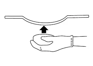
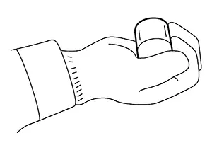
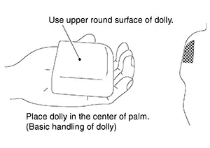
(4) HOW TO HOLD THE DOLLY
Basic handling of the dolly.
(a) TOP:
Place the dolly in the palm of your hand.
Holding it lightly, place the curved surface against the curved surface of the panel.
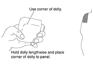
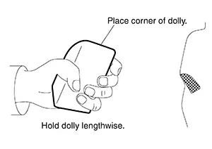
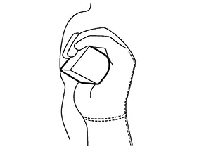
(b) CORNER:
Hold the dolly lengthwise, and place the corner in the sharply bent portion of the panel.
(c) EDGE:
Hold the dolly so that the edge faces upward.
Place this edge to the press line of the panel.
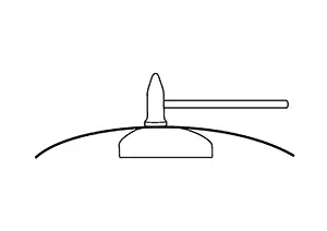
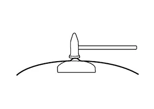
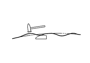
(d) CORRECTING THE PRESS LINE:
To correct a concave press line in a narrow space on the back of the panel, use a dolly as shown in the figure and strike the press line with it.
How to Use Hammer and Dolly
How to Use Hammer and Dolly
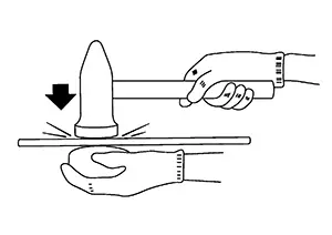
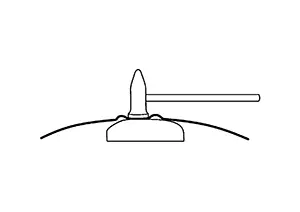
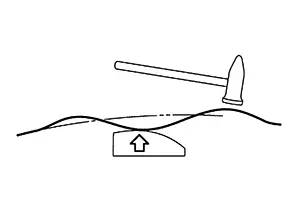
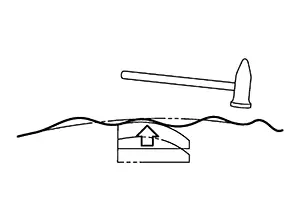
(1) HAMMER-ON-DOLLY
This is also known as dinging on the dolly. The dolly is held directly under the area being struck with the hammer. Hammering smoothes the dented metal between the dolly and hammer. This method causes the sheet metal to stretch.
Hammering on a dolly is most effective for repairing shallow dents.
(a) The hammer strikes the sheet metal, causing the dolly to bounce against the metal surface. Thus the damaged portion is worked out from both inside and outside.
(b) The sheet metal stretches between the hammer and dolly, and deformation is distributed around the strike area.
(c) Continuously move the dolly under the shifting deformation so that it can be struck properly.
(d) The sheet metal gradually stretches and returns to its original shape.
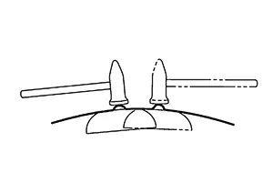
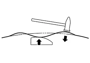
(2) HAMMER-OFF-DOLLY
This is also known as dinging off the dolly.
Place the dolly directly under a dent, and hammer against the edge of the dent. The hammer drives one area downward while the reaction of the dolly drives the adjacent area upward.
An example of the hammer-off-dolly operation is given below.
(a) Place the dolly under the deepest dent, and hammer the highest portion of the top surface.
(b) The raised portion of the surface lowers as it is struck with the hammer.
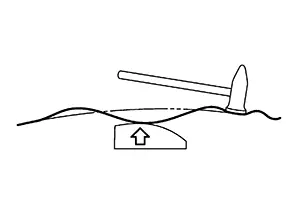
(c) Hammer blows are transmitted to the dolly, creating a reaction force.
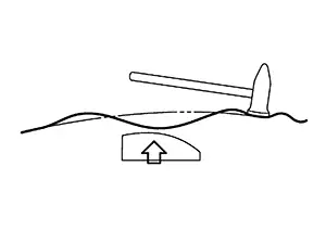
(d) This reaction force pushes the dent.
(e) Repeat steps (a) - (d) until the surface is smooth.
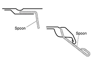
Spoons
Spoons
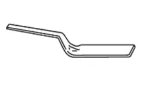
Spoons are made of steel, and one or both ends are flat. Spoons are used as dollies in narrow spaces or as pry bars.
(1) TYPES AND FEATURES OF SPOONS
|
General purpose spoon |
This spoon has a gently curved surface and sharply curved ends. It is widely used in automobile body repair work. |
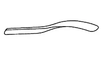
|
Long spoon |
This spoon has a long handle and thin, rigid faces. It is used primarily for prying. |
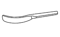
|
Curved spoon |
The handle of this spoon is comparatively short. It has a wide curved blade. This spoon is used for smoothing. |
|
Flat spoon |
This spoon has a short handle and a wide, flat blade. When the spoon is placed on the panel and hammered, the force disperses over a wide area. |
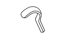
|
High crown spoon |
This spoon has a wide hooked blade. It is used for repairing narrow body panel spaces such as inside of outer sill panel. |
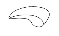
|
Sickle-shaped spoon |
This spoon has a wide, gently curved surface with a thin end. It can be inserted into very narrow gaps between panels. |
(2) SELECTION AND MAINTENANCE OF SPOONS
Select spoons suitable for the particular panel shape and internal structure.
The precautions described for the hammer and dolly also apply to spoons. Do not damage the surface which comes into direct contact with the panel during repair work.
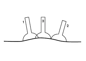
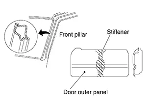
(3) HOW TO USE SPOONS
(a) Insert the spoon into tight spaces such as inside of door, and use as a dolly.
(b) Place a spoon between two panels and pry out the concave portion.
(c) Hammer directly on the spoon to disperse the force of the hammer blows.
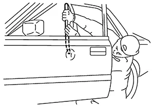
(d) The figure to shows an example of incorrect spoon usage. There is no fulcrum point for the spoon.
If a spoon is used in this way, insufficient force is applied to the mating face, and the spoon cannot act as a dolly.
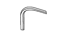
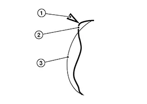
Scribing Chisels
Scribing Chisels
Chisels are generally used to cut sheet metal.
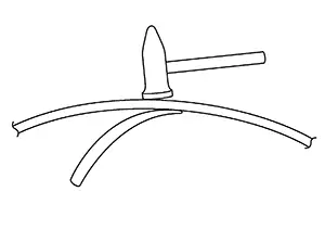
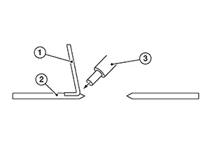
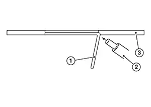
They are also used in body repair work. There are numerous types of chisels. This section, however, describes scribing chisels used exclusively for bending sheet metal or for shaping panel press lines.
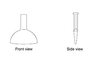
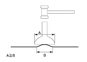
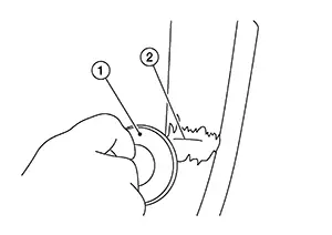
This type of chisel must have a smoothly rounded edge as shown in the figure. If the edge is sharp, the body panel will be nicked.
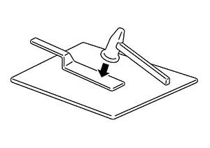
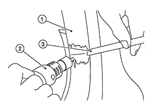
HOW TO USE SCRIBING CHISELS
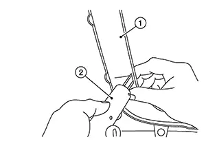
(a) For bending sheet metal
-
First scribe a line on the sheet metal.
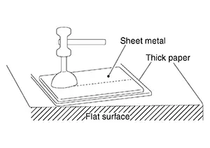
Place thick paper or cardboard under the sheet metal.
Place the scribing chisel on the line and hammer it.
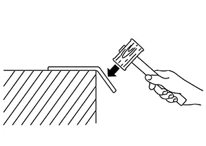
-
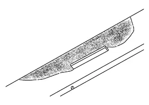
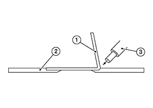
Place the sheet metal on a flat, angled surface scribed-side down, and bend the sheet metal with a wooden hammer.
-
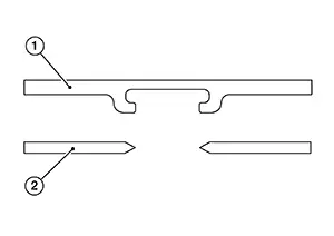
Using a hammer and the scribing chisel, neatly bend the sheet metal squarely. Do not bend all at once.
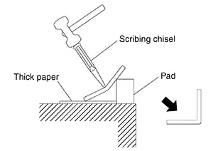
Bend the sheet metal gradually by gently hammering against the chisel head.
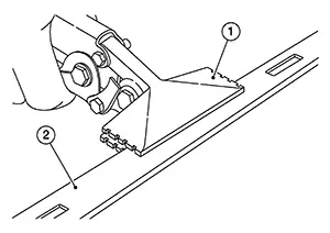
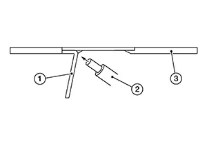
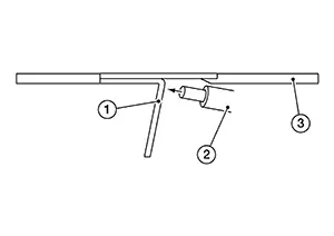
(b) Shaping the press line
-
If the dent in the press line is smaller than the width of the chisel, apply the chisel to the center of the dent. Hammer to flatten. Hammer gently so that the dent can be removed gradually.
-
If the dent is larger than the width of the chisel, do not strike the dent in the center. Apply the chisel at the edges of the dent.
Types and Uses of Tinman Shears
Types and Uses of Tinman Shears
(1) STRAIGHT BLADE SHEARS
For cutting straight lines.
(2) CURVED BLADE SHEARS
The blades are smoothly curved. Suitable for straight or curved cutting.
(3) SCOOPED BLADE SHEARS
The entire blade is bent to one side. Suitable for cutting along a sharply curved line.
Tools for Pulling
Tools for Pulling
If it is impossible to gain access to the damaged area, dents can be pulled out and repaired.
METHODS
There are many techniques to repairing a dent, but there are basically two methods. Both methods can be used depending on the type of damage. Each method has its own advantages and disadvantages.
|
Outside in |
Inside out |
 |
 |
|
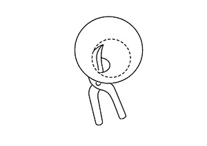
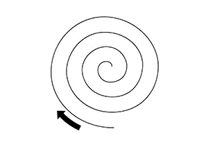
The traditional method is from the outside to the inside in a spiral from. This method has the advantage that the single spots will harden and stabilize the area as you are working into the center. The disadvantage is that the center will be stiffened up and will not be easy to bring out. |
The inside out method is to start in the middle and as it comes out the surrounding area can be worked. Also the hammer can be used at the same time to stress relieve the metal around it. |
If the damage is influenced or affected by an edge or bodyline, you have to go away from the edge - feathering away from the edge with small single pulls.
DENT PULLING TOOLS
|
Damage Level |
Recommended Tool |
|
|---|---|---|
|
Heavy |
 |
Dent pull bar |
 |
Dent pull bar Long bridge |
|
|
Moderate |
 |
Dent pull bar Short bridge |
 |
Slide hammer |
|
|
Light |
 |
Dent Pulling Rod and Hammer |
 |
Dent pulling rod |
|
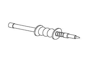
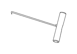
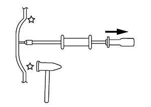
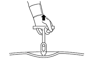
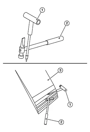
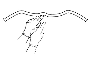
(1) SLIDING HAMMER
The sliding hammer is used for repairing large, deep dents. Since it provides greater force than an ordinary hammer, it is used to repair dents in thick panels.
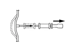
(a) When the panel is thin. Instead of a hole, a metal pin or washer is welded to the panel. Great force can be used for pulling.
(b) When the dent is deep and narrow, pull it with a single blow.
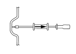
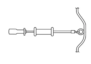
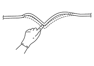
(c) When the panel dent is shallow and wide, hold the end of the sliding handle. Repair the dent by gradually tapping the edge of the dent.
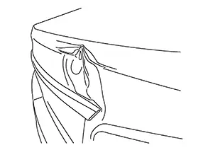
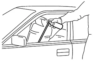
(d) Deeper Damages are pulled out with a hand puller. It allows more of a control and it allows pressure to be applied and at the same time the pressure can be applied with the hammer.
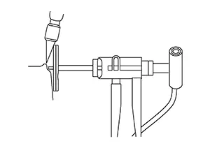
A hand puller has the advantage with a line damage. The damage can be pulled up with more control and will reduce the repair area.
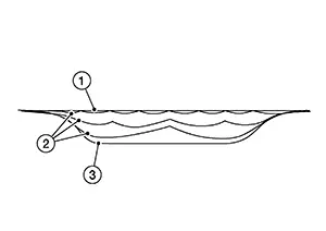
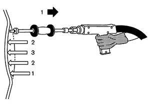
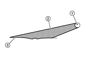
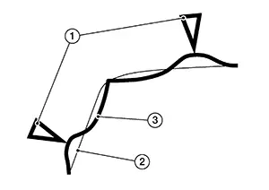
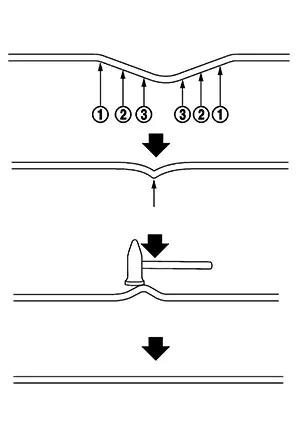
Repairing long dents or deep dents
If the damage is deep don't try to pull up the damage completely. Do it in increments until the desired level is achieved .
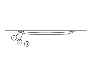
|
1 |
:Panel surface |
|
2 |
:First pulling distance |
|
3 |
:Finishing pulling distance |
Pull first in the middle with a light pull. Then continue by halving the distance between the pulls always pulling a little every time. Don’t try to pull it all at once, because the metal will be too high at the end.
|
1 |
:Finishing pulling distance |
|
2 |
:Pulling distance by halving |
|
3 |
:Panel surface |
When using the hand puller, place the feet cross to the bodyline.
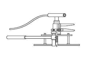
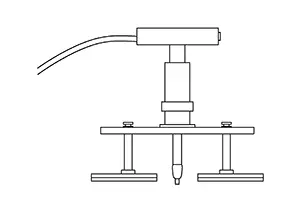
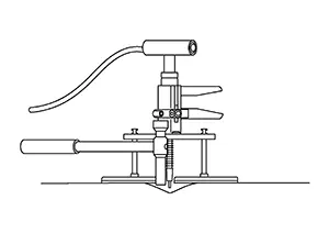
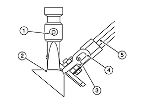
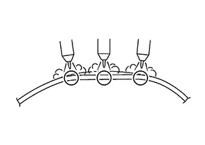
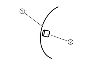
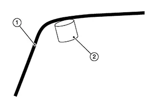
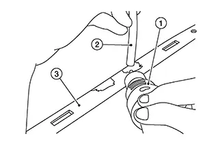
(2) STUD WELDER (BODY REPAIR STATION)
A pin or washer is welded directly to the body panel dent without drilling. The panel dent area is then pulled outward with the sliding hammer. Because no drilling is required, panel strength is unaffected. Corrosion problems are also reduced.
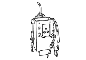
Application of the clamp for ground will increase the painting area in the repair process. A different ground could be used which can be applied next to the damage and will reduce the repair area.
Because the stud welder welds pins directly, the paint must be removed from the dent surrounding area and the area where body ground is established.
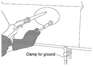
As shown in the figure, the ground can be established at the flange area or in the dent surrounding area using a magnet.
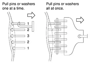
(3) WELDED PIN OR WASHER
A pin or washer is welded to the dent without drilling. It is then pulled to repair the dent.
Several pins or washers are welded to the dent. They are then pulled together or separately to repair the dent.
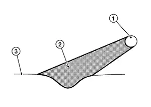
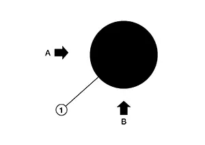
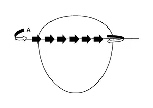
Analyze
Look at the damage. See from which direction the hit came from and the extent of the damage. Also look for the different zones.
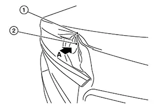
|
1 |
:Crown (metal pushed up) |
|
2 |
:Damage |
|
A |
:Direction of impact |
If there is an edge or bodyline within the damage area, it is important to focus on straightening it first as shown.
|
1 |
:Finishing pulling distance |
|
2 |
:Panel surface |
In most cases, there is also a crown (1) in the damage. The crown is the area where the metal has been pushed out. Depending on the shape of the metal and the direction of the hit the crowns are in different areas.
|
2 |
:Finishing pulling distance |
|
3 |
:Panel surface |
To bring out the edge or the bodyline a bridge system is ideal. The advantage of a bridge system is that you can bring out the edge first and relieve pressure on the crown.
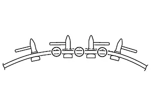
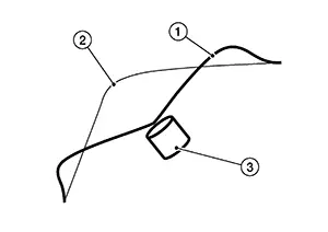
Welding on the Bits
It is important to weld on the line. Therefore, first mark the line by using the pulling bar and making a scratch on the bare metal. You can also use the Flatliner Laser to make the line. Welding of the bits is done most of the time on the tangent point (2) of the line. This depends on the direction of the hit. Try not to weld on the radius area (1) or round area of the bodyline. This will increase the risk of making a hole in the panel.
Welding on the bits is easiest done with the Bit Gun. You can also single weld this. On the Digispot, change to manual welding mode, this way you can first place the bit and then weld. In the area where you don’t need a lot of pulling force you can place the bits further apart. In the center where more pulling force is needed try to weld the bits as closely together as possible. The more bits you weld on and the closer they are, the fewer waves you get in the repair.
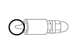
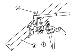
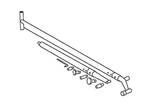
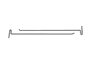
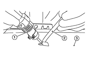
Insert the pulling bar (1). There are 6 different types of pulling bars (2): three different lengths and also either straight or bent at the end. The bent pulling bars are for vertical applications.
Note:
For a low pulling force, individual weld on tabs (3) can be pulled. For a high pulling force, multiple weld on tabs can be pulled.
|
4 |
:Panel surface |
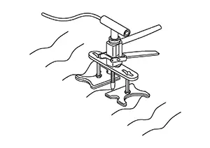
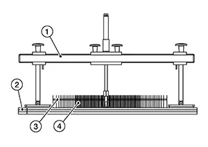
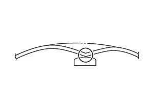
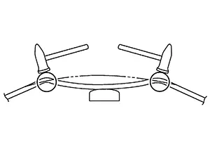
Applying the Bridge
For small areas, it is best to use the FL80-bridge. Also use the 2 angle directional feet (1). This way the bridge will not tilt down during the pull.
|
2 |
: Panel surface |
|
3 |
:Weld on tabs |
Open up a space for the pulling bar (1) in the middle of the panel surface (2).
Place the feet on the outside of the damaged area and apply a little pressure by rotating on the pulling mechanism.
|
3 |
: Bridge |
|
4 |
: Weld on tabs |
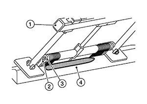
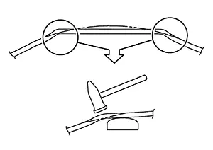
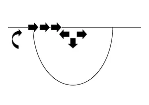
When you pull up the damage, don't pull it out completely. Once you get a little tension on the pulling mechanism it is important to start to relieve the tension on the crown. This means that you are pulling a little and knocking down on the crown in direction shown.
|
1 |
:Panel surface |
|
2 |
:Finishing pulling distance |
It is easiest to use two hammers (1) at the same time. One is for placing and the other for hitting. If you use the vertical fin of the hammer and place it on the crown (2) you can see the crown much better from the side, even if it is a small crown. The other advantage of using two hammers is that it will reduce the vibration, which can loosen the bits.
|
3 |
: Weld on tabs |
|
4 |
: Pulling bar |
|
5 |
: Bridge foot |
Try to pull out the damage a little and knock down the crown again. You will feel the pressure on the pulling mechanism releasing once you take away the tension from the crown.
|
1 |
: Hammer |
|
2 |
: Panel surface |
|
3 |
: Pulling bar |
|
4 |
: Weld on tabs |
|
5 |
: Bridge foot |
Once most the damage is pulled up and the crown is knocked down, check if the line is straight. You can do this with a pulling bar or with the laser.
|
1 |
: Bridge |
|
2 |
: Panel surface |
|
3 |
: Pulling bar |
|
4 |
: Weld on tabs |
The next step is to bring out the remaining area and to stabilize the edge. This is normally done on both sides of the damage. This is done while the bridge is still in place. It will hold the line and facilitate the repair process of the area.
|
1 |
: Bridge |
|
2 |
: Pulling bar |
|
3 |
: Weld on tabs |
|
4 |
: Panel surface |
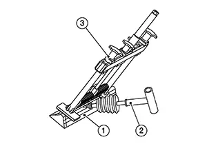
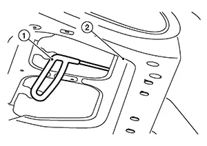
Depending on the depth and strength of the remaining damaged area (1) different tools maybe be used. It is best to use the T-Handle (2) or if needed the small sliding hammer of the Innopuller. Normally not much force is required.
|
3 |
: Bridge |
The rest of the finish can be done with the Innopuller or the hand puller (1). Another option, if the damage (2) is still deep, is to use the Innopuller with the hammer (3).
Bridge Application Short
On rocker panels and edges or in small places most of the time the FL80-bridge is being used.
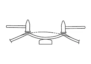
Bridge Application Long
On larger areas or where the damage is in the middle of the panel the FL120-bridge is being used.
(4) SPOT HAMMER WELDING
The sliding hammer tips are welded to the dent.
They are then pulled separately to repair the dent.
After the tips are pulled, they are twisted to separate them from the panel.
(5) HAND PULLER
The hand puller (1) can also be used together with the hammer (2). By applying a little pressure on the handle and with little hits from the hammer the stress can be relieved. This can also help with frogs/oil canning in the metal.
|
3 |
:Panel surface |
The finish is best done with the hand puller/T-bar and the hammer. Start from somewhere on the outside and work your way in. It is also helpfull to place the Flatliner Laser further away and to run the light over the surface.
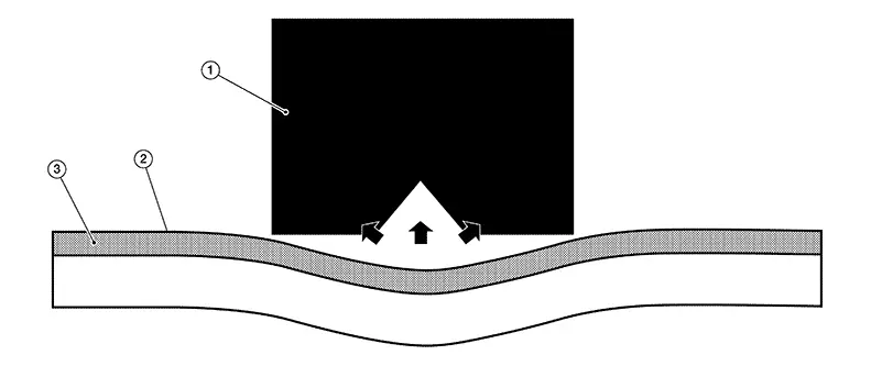
Hotbox dent removal
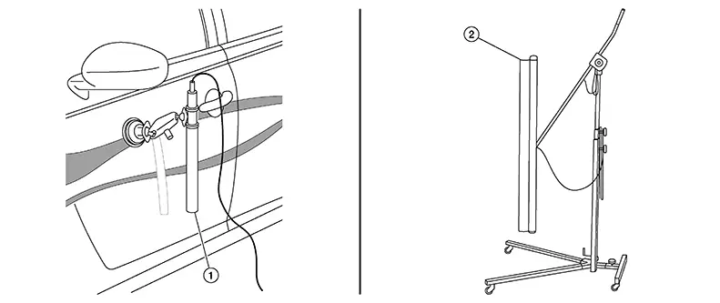
The dent removal with induction heating works on the basis of surface heating of the sheet metal (1). By using a certain frequency the surface (2) of the sheet metal gets activated so that the top surface of the sheet metal is heated and thus expands. The other key working function is the vibrating impulse in the tool which helps the process.
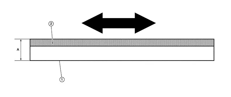
|
A |
0.7mm (0.028 in) |
This effect makes it ideal for the rising of soft damages.
|
1 |
:Hotbox |
|
2 |
:Sheet metal |
|
3 |
:Surface |
-
There are four applications
- Soft dents
- Dent reduction of larger or sharper dents
- Area work or cleaning up an area that has been repaired by the dent removal tools or glue system.
- Shrinking or stiffening of metal
-
The use of each applications
Soft dents or elastic dents can be repaired as long as the metal is not stretched and or that the main stress on the metal is not larger than the pulling force of the Hotbox effect.
With dents which have a plastic deformation or dents which are larger or where the center is stretched, the energy part (plastic deformation) of the dent cant be removed, as long as the main stress on the metal is not larger than the pulling force of the Hotbox.
After a dent has been repaired by the dent tools or the glue system, it often happens that the general area is still low and might have some waves in it. Then this area can be easily brought up by the Hotbox.
If by large dents the damage was that large that the mechanical strength of the material has been weakened, then the Hotbox can be used to shrink this area, best done by applying the tool to the center and then heating it to the maximum and then to cool off with cold air or water. This is best done more than 3 times to get the stiffness into the metal.
The setting of the unit as far as the power is concerned is always 100% with the Hotbox. With the T-Hotbox the power setting is always 100% if the time functions is being used.
-
The Applications
-
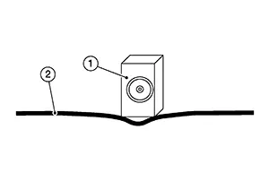
Application (Small soft dents)
Don’t press the heat pen (1) on the metal (2). Just hold it on top and as the metal comes up pull up the tool head.
- Application (Large soft dents)
1
:Hotbox
2
:Sheet metal
Start on the side with a short impulse. Depending on the size of the damage it might be necessary to start far away from the center of the dent as shown. The impulse should sound like a beebeep (2 Beeps). This is about .1 sec pressing the red button on the hotbox (1). Always use the light and look on the surface to see what the metal (2) is doing.
If the metal is going down, go further away. Also check if there might be a brace behind it, or maybe the damage might be too large.
1
:Hotbox
Then move closer to the dent, and again a short impulse (bee-beep). It is important to do an impulse on the edge or almost going down into the center of the dent.
1
:Hotbox
2
:Sheet metal
Then once the metal has come up, bring up the center by heating for at least .6 sec. The metal should be over-pulled. Also the raising of the metal can be done by short impulses, always raise the tool to see what the metal is doing. This will take some practice.
-
Shrinking the Sheet Metal
Shrinking the Sheet Metal
Shrinking The Sheet Metal
Plastic deformation may cause reduced panel thickness and the panel may stretch. Even when it is repaired using a hammer and dolly, the panel tends to bulge, losing its original shape.
In such cases, it must be shrunk to its original shape. This is called shrinking the sheet metal.
Shrinking Methods
Shrinking Methods
(1) ELECTRIC WELDING MACHINE
The body panel is connected to the negative power supply terminal and the tip is connected to the positive terminal. Then, an electric current is supplied to heat the panel. The shrinking principle is the same as that of gas welding. This method features no hammering and greater workability than gas welding and is suitable for repairing local panel deformations.
(2) CARBON ROD
The panel is connected to the negative power supply terminal and a carbon rod is connected to the positive terminal. The panel is heated so that heat is conducted from the outside to the center of the dent. Wet rags are then applied to cool it quickly, thus shrinking the panel.
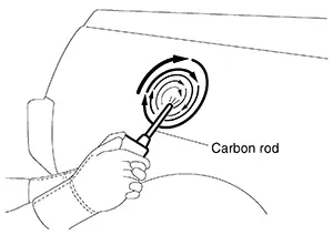
This method is suitable for repairing wide, shallow panel deformations.
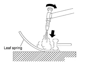
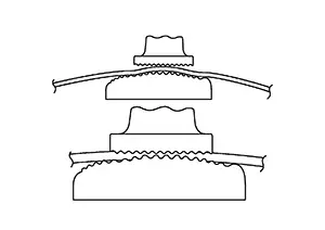
(3) GAS WELDING (OXY-ACETYLENE TORCH)
(a) Heating and expansion
As the sheet metal is heated with a gas welding torch, it stretches.
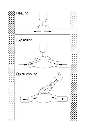
However, stretching is restricted in the unheated surrounding portion. As a result, the heated portion bulges.
(b) Sudden cooling
When the bulge is cooled suddenly, it shrinks.
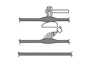
This shrinking is accelerated by tapping with a wooden hammer.
(4) HAMMER AND DOLLY
A shrinking hammer and shrinking dolly are used by the hammer-on-dolly method. Many tiny dents are formed on the panel surface. This method is suitable for shrinking comparatively small areas of panel deformation.
How to Heat Sheet Metal
How to Heat Sheet Metal
-
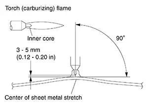
Use a carburizing flame when shrinking sheet metal with a gas welding torch.
-
Hold the torch at a right angle to the center of the sheet metal.
-
Maintain a distance of 3 mm - 5 mm (0.12 in - 0.20 in) between the inner core and sheet metal.
-
Heat the sheet metal to approximately 800°C (1,472°F) (until the heated portion turns red). Increase the temperature if sheet metal stretching is insufficient.
-
Locate the stretched portion of the panel.
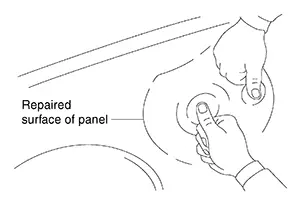
Press the surface being repaired in several places.
The point where the largest elastic dent is formed is the center, where the stretch is the maximum. The highest portion of the panel being repaired can also be considered the most stretched portion.
-
The area heated with a welding torch must be approximately 3 mm - 5 mm (0.12 in - 0.20 in) in diameter if the panel shape is complex, and approximately 6 mm - 15 mm (0.24 in - 0.59 in) in diameter if it is flat.
-
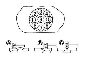
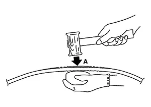
Small stretch
-
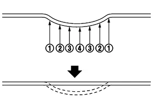
Apply a dolly to the back of the heated panel. Tap the panel with a wooden hammer using the hammer-ondolly method in the sequence shown in the figure.
(A) and (B) → 1 - 8
(C) → 9
-
Excessive stretch
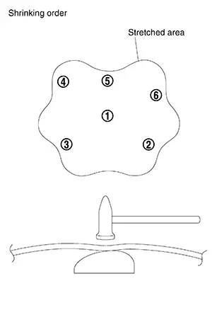
Shrink the panel, starting with the most stretched portion, and proceed toward the edge of the dent so that the dent surface is lower than the original surface.
Using a gas welding torch makes the panel concave.
To correct this, strike the concave portion using the hammer-on-dolly method to stretch the panel bit by bit until the original surface is restored.
-
Apply wet cloths to the shrunken portion of the panel to cool it quickly.
Correcting a Deformed Exterior Body Panel
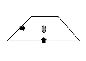
Determining Panel Damage
Determining Panel Damage
CAUTION:
This repair method should not be used on rails and reinforcements.
Panel damage must be examined carefully to select the most suitable repair method.
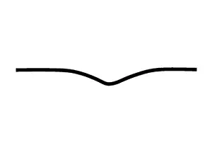
(A) In the figure is the plastic deformed area and the surrounding portions are elastic deformed areas.
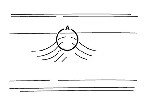
Correction of (A) will automatically remove the elastic deformation.
Removing the cause of the dent can simplify the entire repair operation. Plastic deformation can be recognized by sharp bending, a nick, or cracked or peeled paint.
SHEET METAL DEFORMATION ANALYSIS
(a) When external force is applied, sheet metal deformation begins. Elastic deformation is generated around the point where the external force is applied.
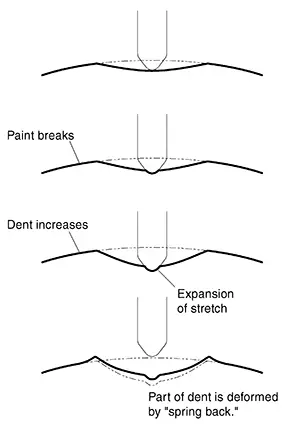
(b) As the external force increases, areas surrounding the dent yield to the pressure, and local cracking or small breaks in the paint occur. This indicates plastic deformation.
(c) If the external force continues to increase, breaks around the dent enlarge, and the sheet metal at the center of the dent stretches.
(d) When the external force is removed, the “spring back” causes the plastic deformed portion of the dent to swell above the original surface.
Basic Types of Damage
Basic Types of Damage
The first thing we look at is the dent. This is also the case when you repair a dent. You always should look at the damage first. The important thing to look at is the center of the dent. The depth of the dent is the important part. It tells you the following:
- Difficulty of the repair
- Time of the repair
- Type of repair method
There are many different aspects to dents but the depth is the most important part. On one side it is the depth and on the other side the sharpness, but in most cases a deep dent is also a sharp dent. Basically there are two types of dents.
Depending on the type of dent you want to repair, consider the following information:|
Sharp Dents |
Soft Dents |
|
 |
 |
|
|
Repair Time: |
2x (twice as much time as soft dents) |
x |
|
Repair Method: |
Levers |
PDR, Glue System |
|
Technical Experience: |
Medium to high |
Low to medium |
|
Cause of Damage: |
Park, medium to big hail |
Soft park, small to medium hail |
-
Soft or Shallow Dent
Most of the shallow dents have a low depth. They are also called elastic dents.
-
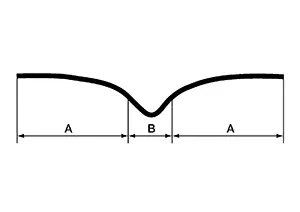
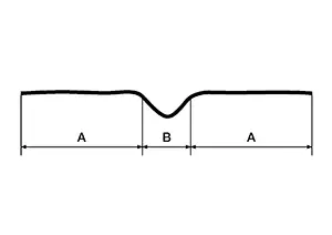
Sharp Dent
A sharp dent is made out of two parts: The Center (A), which is formed by the object which made the dent (stretched metal) and the second part of the dent (B), which is from the energy of the hit.
-
Energy of the hit
A:
Primary Damage - Stretched center plastic deformation
B:
Secondary Damage - Energy of the hit elastic deformation
The outside part (A) of the dent is removed quickly. That is the easy part. To remove the center (B) is more difficult and needs more experience.
CAUTION:
This repair method should not be used on rails and reinforcements.
-
Plastic deformation forms at the center of portion (A) of the dent. The surrounding area remains in elastic deformation.
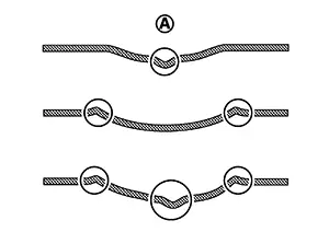
-
Plastic deformation occurs at one or several portions around the dent. Other areas remain in elastic deformation.
-
Both plastic and elastic deformation are generated throughout the damaged panel.
Examination of Panel Damage
Examination of Panel Damage
CAUTION:
This repair method should not be used on rails and reinforcements.
It is difficult to find minor deformation or panel irregularity, particularly, at the final stage of repair. This section explains how to determine if a Nissan Sentra vehicle has minor panel deformation.
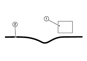
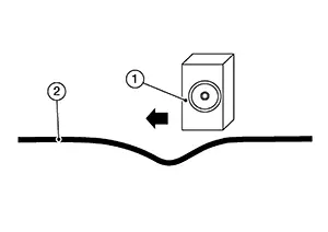
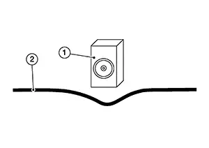
(1) VISUAL CHECK
Check the affected portion of the panel by carefully examining the deformation in the light reflected on the surface.
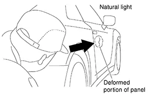
(2) What is Light? (General Contrast)
One of the major weak points is not being able to see the extent of the damage and correctly analyzing the damage and repair process.
For this it is necessary to look at the panel correctly.
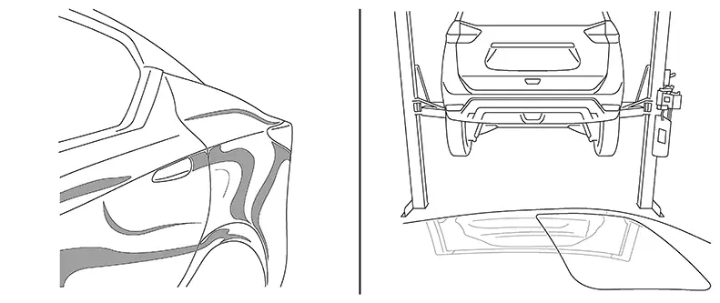
The basic of a light is the contrast and a line. The bigger the contrast the better you can see the damage. At first use a light contrast in the distance to see the damage. Use the contrast as a scanner which you can move over the surface.
Once you have found a good contrast line (A) it can be used to see the damage precisely (B). The most ideal would be to use a PDR type light as with it you will be able to see the full extent of the damage.
At first use a light contrast in the distance to see the damage.
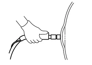
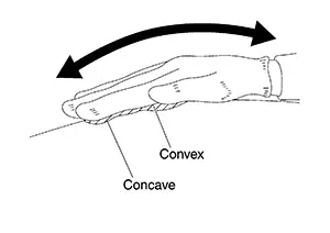
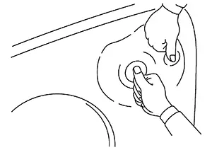
(3) TOUCH CHECK
Lightly place a hand on the surface of the panel and move it forward/backward and right/left to judge by touch with the palm of a hand. Slide and move a hand from an undamaged surface to a damaged part, all the way to the undamaged surface on the other side.
Note:
Wearing work gloves makes it easier to tell the difference.
(3) CHECK WITH PAINTLESS DENT REPAIR (PDR) LIGHT
Refer to Light Stand.
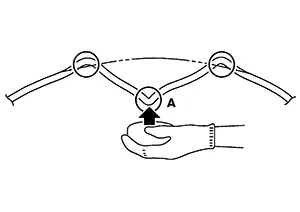
Elastic Vs. Plastic Deformation
Elastic VS. Plastic Deformation
-
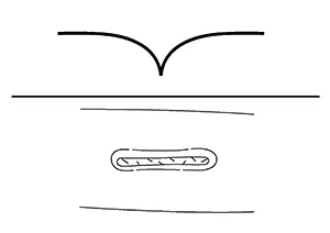
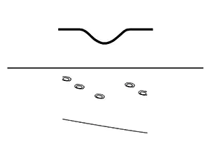
Elastic deformation: If pressed, the deformed portion will move or further deform.
-
Plastic deformation: If pressed, the deformed portion will remain unchanged, and other portions will move.
Basic Repair Procedure
Basic Repair Procedure
(1) WHEN PLASTIC DEFORMATION OCCURS AT THE CENTER OF THE DAMAGED PORTION
(a) Using a hammer or dolly, strike the lowest portion of the dent from behind until it becomes flat.
(b) Using the hammer-off-dolly method as shown in the figure, raise the concave portion and lower the convex portion.
Then smooth the surface a little lower than the original. Using a wooden hammer and dolly, correct the irregularities in the panel.
(c) Existence of plastic deformation can be determined by the stretched panel. The original surface can be restored by shrinking that portion with a gas welding torch.
(d) Use a hammer and dolly by the hammer-on-dolly method. Stretch the panel while striking the outer area of the damaged portion. The entire panel surface should be formed somewhat higher than the original surface. Note that, in this case, the stretched portion of the panel must not be hit with the hammer.
If the concave portion is shallow and if the working face of the wooden hammer matches it, the repair work can be completed quickly by directly shrinking the portion with a gas welding torch.
(2) WHEN PLASTIC DEFORMATION EXISTS AROUND THE DAMAGED PORTION
(a) Apply the dolly to the elastic deformation area behind the panel. Hit the plastic deformation area with a hammer so that the elastic deformation area is lower than the original surface.
(b) Repair the plastic deformed portion using the hammer-off-dolly method. If a shrinking hammer is available, the stretched portion can be easily shrunk.
(3) WHEN PLASTIC DEFORMATION EXISTS AT THE CENTER AND AROUND THE DAMAGED PORTION
(a) Using a hammer and dolly, flatten the lowest portion (A) where the plastic deformation exists, so that the flattened surface is not higher than the original surface.
(b) Flatten the highest points (B) where plastic deformation exists.
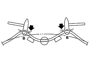
(c) Flatten portion (A) so that the panel surface is not higher than the original surface.
Correct irregularities using a wooden hammer and dolly. If the panel has been stretched, repair by shrinking.
(4) CORRECTING PANEL DISTORTION
(a) Panel distortion occurs when panel damage is repaired. The panel is deformed within the range of elastic deformation. If pressed with a finger, the deformed area bends inward and outward. Panel irregularities occurring over a wide range other than the repaired portion may also indicate panel distortion.
(b) Cause of panel distortion
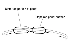
Expansion stress due to damage repair is confined inside the panel because the outer area is bent and work hardened. Thus, it does not allow the panel to expand. The stress is released in the form of panel distortion.
(c) How to correct panel distortion
Panel distortion can be removed by shrinking the stretched portion or by stretching the side of the press line using the hammer-on-dolly method.
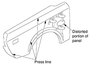
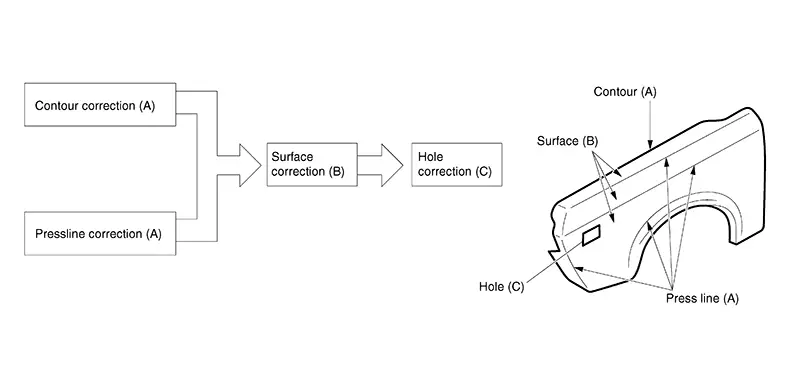
The front fender repair procedure is explained below:
When repairing the body panel, paint and anti-corrosive wax must be thoroughly removed from the damaged area by sanding.
Paintless Dent Repair
Paintless Dent Repair
Paintless Dent Repair
Paintless dent repair is one type of panel repair technique. This technique is used to repair irregularities on painted outer panels without damaging the painted surface.
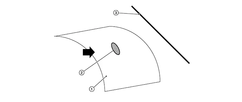
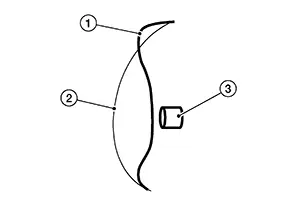
Confirmation of the Panel
Confirmation of The Panel
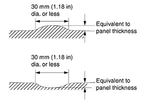
It is not possible to correct all convex/concave portions in paintless dent repair.
Whether or not the parts need to be removed/installed, and tools that can be inserted must be checked for each repair location.
When checking the convex/concave location, determine whether or not the paintless dent repair is possible. It is also important to determine the most suitable repair method.
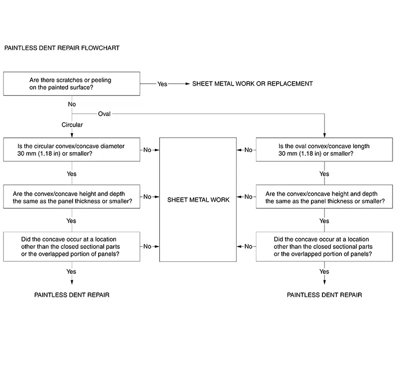
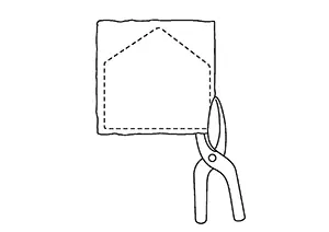
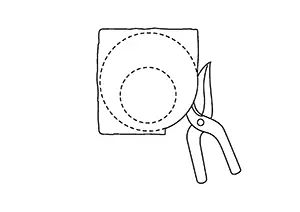
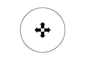
|
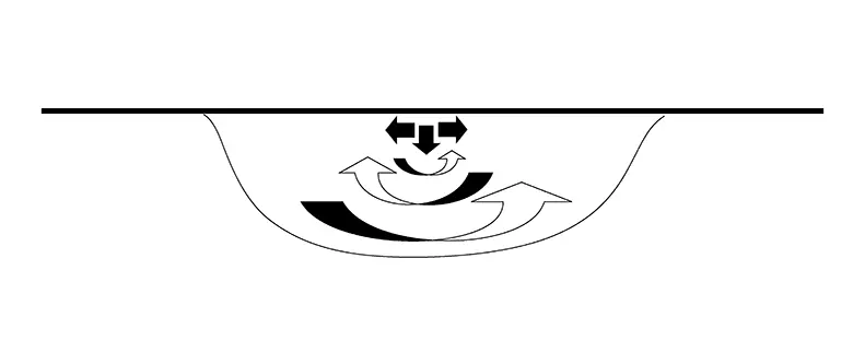
Example of circular convex/concave |
Example of oval convex/concave |
|---|---|
 |
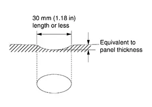 |
Light Stand
Light Stand
Over the years the light system has evolved from a single neon to multi lines and then to the reflector type light.
|
Small Light (1) |
Large Light (2) |
||
|
Advantage |
Disadvantage |
Advantage |
Disadvantage |
|
|
|
|
Most professionals use a large light because of its many advantages.
Light Position: 3 Points
There are several aspects to consider in setting up the light. This is the main problem area for beginners. It looks easy but it is not. We are looking at three aspects in the setting up, which are crucial to the success of a proper repair.
-
Distance (Angle)
Beginners often place the light too close.
There is no precise distance for the positioning. In a repair the light should always be positioned in two distances. First close, to see the tool a little better and also to be able to see into the dent. Although if the dent is to deep or big the center of the damage can’t be seen in the light reflection.
-
Normal distance: First position
1
:Light source
2
:Light
3
:Surface
-
Finishing distance: Second position for the finish
In the finishing stages of the repair the light should be moved to the distance, as this will show the minor imperfections and the general area much better.
1
:Light source
2
:Light
3
:Surface
1
:Normal or start position
2
:Finishing position
-
-
Light Position Parallel
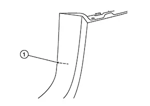
Always make sure the light (1) is parallel to the surface (2) which you are repairing.
-
Top or flat surface
-
Side or curved surface
1
:Light source on a curved surface
2
:Light source on a side surface
3
:Surface
It is ideal if the light system being used is easily adjustable to be able to match the contour of the car body.
Consider which way the metal is bent.
If the panel or area is flat it doesn’t matter from which direction the dent is repaired.
But if the panel (1) or area is bent it is important to work perpendicular to the bend. The reason for this is that from the front, the dent (2) can’t be seen well with its full size.
3
:Light source
-
-
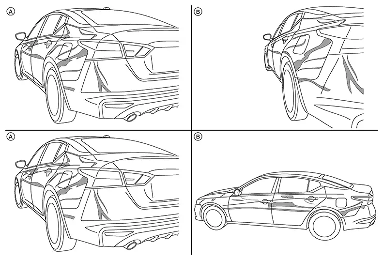
Light Position Crisscross
It is always important to work the dent (1) from two angles (A and B). This is mainly the case for top panels like the hood, roof and trunk. The reason for this is that the dent can’t be seen completely from one side. Therefore you first work from one side. This is normally done with a light position with a normal angle (A) and you fix the dent up to 80%. Then you change to angle (B), ideally 90°, and finish the dent from the other side keeping the light at a distance.
Selection of Repair Tools
Selection of Repair Tools
Tools for paintless dent repair are hammers, spoons, dollies and punches. Some popular hand tools for paintless dent repair and application examples are described below.
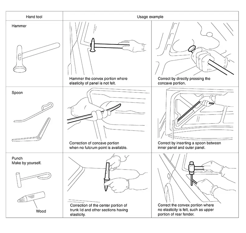
Choose suitable tools to repair the panel.
There are three basic tools being used. Levers, Glue System and Hotbox. The choice of tools will depend on the access to the damage and experience level of the technician.
|
Levers (Paintless dent repair) |
Glue system |
Hotbox |
|
|
Access |
95% (Roof rail) |
30% |
10% |
|
Experience |
6 months |
2 days |
½ day |
|
Training/Practice |
2 days (6 months practice) |
½ day |
½ day |
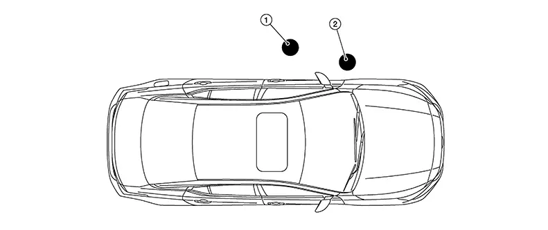
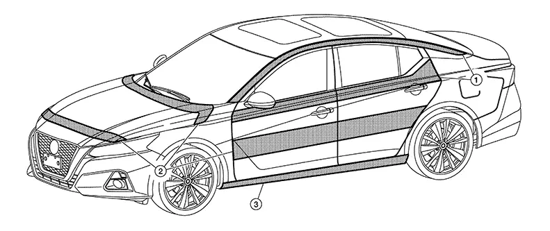
Difficult Areas to Repair Dents on
|
Index |
Explanation |
|
1 |
This area is difficult to repair due to access. Often the glue or Hotbox has to be used and with sharp dents it is limited |
|
2 |
This area is difficult due to braces. It can be done with PDR but often the brace is in the way. |
|
3 |
This area is also difficult to repair due to the double brace in the rail. Most of the time this area is done with the glue system |
-
Levers
Levers (1) are used in the open areas like on hoods, roofs and also on side panels without any braces.
Standard levers
Next to that there are tools which are mixed like the hook tools.
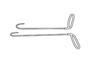
Then there are also special lever tools with different tips.
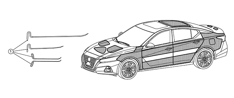
-
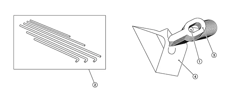
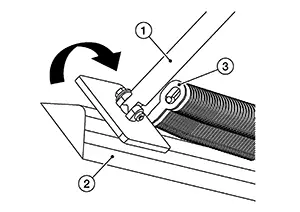
Wire tools
Wire tools (1) are used in areas which you can’t reach with lever tools. This is the case mostly behind braces or on tight places.
Standard Wires
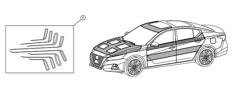
-
Long wires
-
Tips of wire tools
Most tips on the wire tools are very similar due to the construction. The contact area is about 1mm. In order to make it soft, often tape is used.
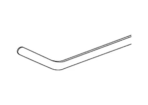
Another important point is the shaving along the tool (1) shaft. It makes the access into the braces (2) much easier.
Panel Repair Methods
Panel Repair Methods
(1) CORRECTION OF CONCAVE PANEL WITH SPOONS
Convex panels can be repaired with a hammer and punch. Concave panels can be repaired with a spoon if the following conditions are satisfied:
-
The spoon must be able to be inserted behind the concave panel. A closed construction portion or mating panel cannot be repaired.
-
Use of lever action should be allowed.
If the surrounding portion of panel can be used to support a spoon as a lever, the concave area can be repaired. Otherwise, corrective force cannot be transmitted to the desired portion.
-
The concave portion should be visible from outside.
This work is performed visually, and dents in concealed areas cannot be repaired.
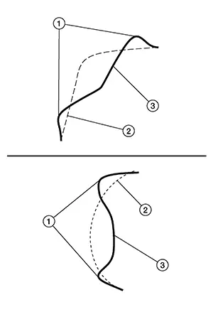
(2) KEY POINTS IN PAINTLESS DENT REPAIR WORK
-
Repairing Larger Damages:
Especially on large dents or on dents over metal which has a bent form, the damage created a crown.
Meaning the metal was pushed to the side and deformed. First, push out some of the center (50%). Look for the crown and knock it in. Then push out the damage again. Depending on the damage, this has to be done several times, between pushing and knocking down.
1
:Original damage
2
:Finish pulling distance
3
:Tool
1
:Knock down the crown
2
:Original damage
3
:Finish pulling distance
1
:Finish pulling distance
2
:Tool
-
Repairing Dents over Edges:
-
Start position (A).
-
Position outside in the open
1
:Original damage
2
:Finish pulling distance
3
:Tool
-
Move to the edge
-
Move slowly along the edge, back and forth.
-
The edge has to come up first.
-
Knock down the crowns (1)
2
:Original damage
3
:Finish pulling distance
-
Push up the rest
1
:Finish pulling distance
2
:Tool
-
-
Repairing half moon dents or dents away from the edges:
-
Position on the outside
-
Move to the edge
-
Go to the center
-
Push out from the edge and the center to the outside
-
-
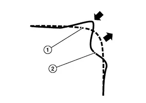
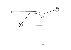
Repairing a smoothly rounded concave section:
Raise the concave portion little by little, beginning with the outside.
-
Repairing a concave section bent sharply at the center:
First, raise the concave portion 60% - 70%, beginning with the outside. Next, raise the sharply bent portion slightly higher than the surrounding panel surface.
Then flatten the high point by tapping with a hammer.
-
Do not attempt to correct panel deformation all at once.
Use the step-by-step repair method, such as roughing → smoothing → finishing.
-
After repairing, visually check the repaired portion from all directions.
Polishing of Panel Surface and Anti-Corrosive Treatment
Polishing of Panel Surface and Anti-corrosive Treatment
(1) POLISH-FINISHING OF CORRECTED SURFACE
If the painted surface is scratched during repair, polish with compound to remove scratches.
(2) ANTI-CORROSIVE TREATMENT OF BACK OF PANEL
The spoons may cause scratches. Apply anti-corrosive wax to the back of panel.
Use 3M 8852 Cavity Wax + 3M 8851 Applicator Wand Kit, or equivilent.
Examination of Panel
Examination of Panel
Irregularities in the panel must be examined carefully to see whether or not they can be repaired, and also to determine the most suitable repair method.
Refer to "Examination of Panel Damage".
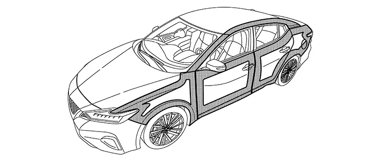
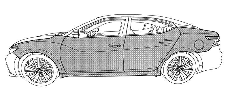
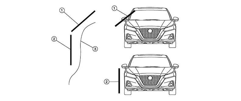
Work Direction on a Nissan Sentra Vehicle
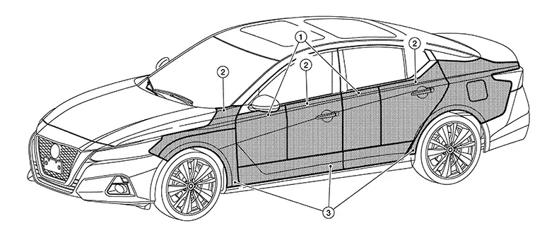
|
1 |
Area mainly accessed from the back to the front |
|
2 |
Area mainly accessed from the front the back |
|
3 |
Area mainly accessed from the bottom |
For each panel and each general part of a panel it is important to consider the light position, direction of the light position and the work direction.
Glue System
Glue System
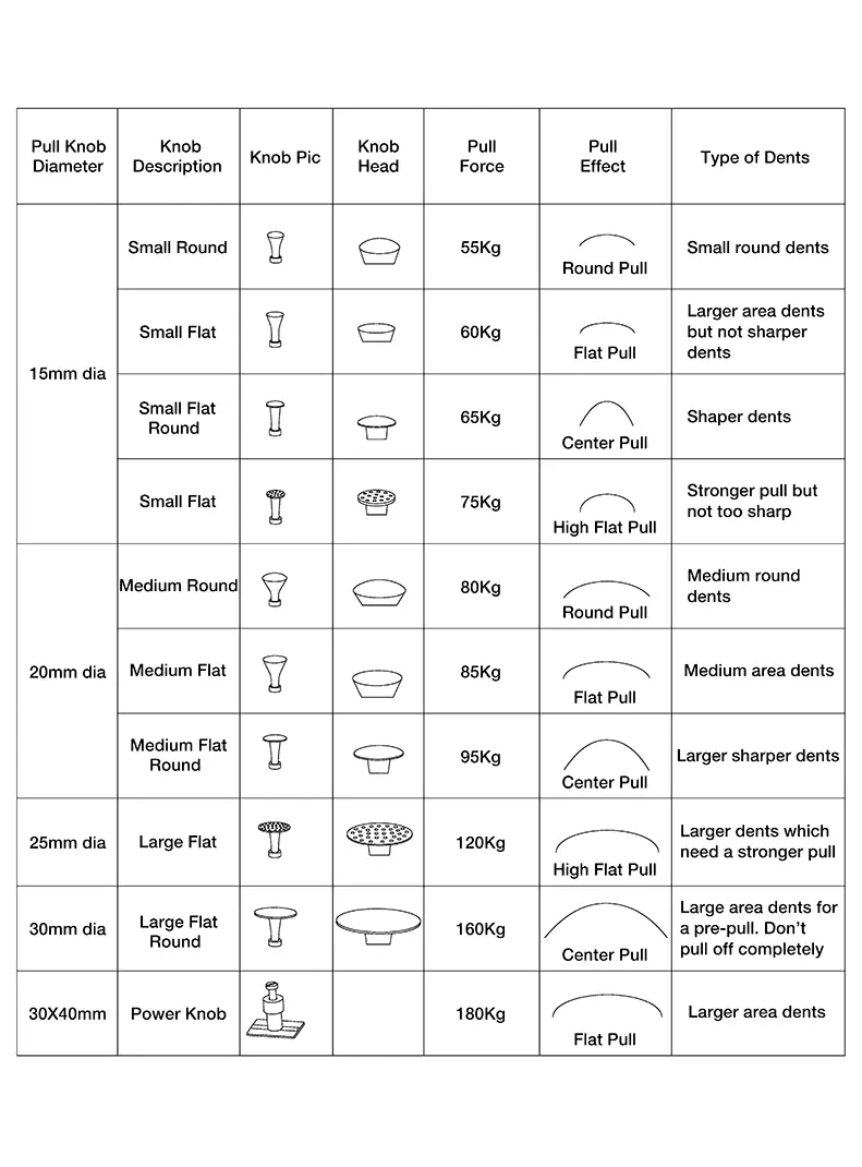
Glue systems allow pulling when an area is not easily accessible like roof rail or beneath braces. It is also one of the easiest systems to learn. But it is mainly limited to soft dents.
A couple of things that affect the glue pulling:
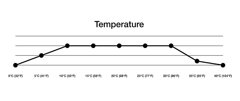
-
Temperature
The diameter and the size of the pull knob
-
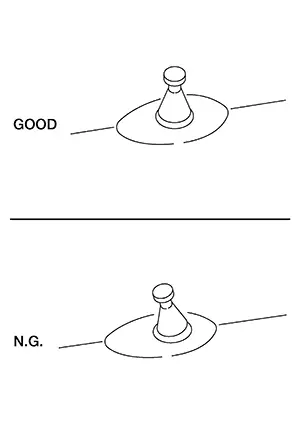
Application
Place the knob correctly.
-
Cooling time
The cooling time depends on the surface temperature as well as on the type of glue being used. The glue is coming out of the glue gun from 120 deg. to 140 deg. depending on the glue gun. Then the glue needs some time to cool off. There are several methods as to when to pull also depending on the type of glue.
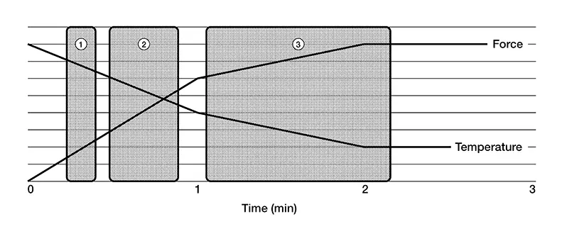
Index
Explanation
1
After 15 seconds: In this range, a pull can be done if a high pulling force is not required, for example, with small dents.
2
After 25 seconds: In this range, the warmth of the glue can still be in the metal, and thus facilitate the pull. This can only be done with sharper dents. With some glues, this can be the ideal cooling off time.
3
After 60 seconds: This is the standard range if you want consistent results.
-
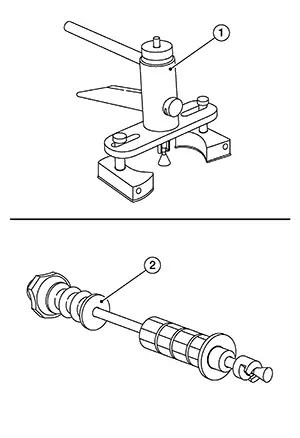
Pulling type
There are two basic pulling methods. One is with a hand puller and the other is with the sliding hammer.
In general the hand puller (1) is easier for beginners and also for deeper damage. The sliding hammer (2) is a little faster in the application. It depends more on what you are used to.
-
Area of application
The glue system can be used on all areas. It is ideal on soft and medium dents. Although in some areas where access with the PDR tools is difficult it is used frequently.
Plastic Repair
Plastic Repair
Plastic welding can be used as a repair method only on thermoplastics.
Work preparation
Repairs must always be carried out from the inner to the outer side of the component, which means that in most cases, it is necessary to disassemble the damaged body component.
The repair area must always be thoroughly cleaned prior to any repair.
To ensure that there is a good bond between the plastic and the filler material, the edges of the break must be sanded into a wedge or "V" shape on the inner and outer sides. in addition, the paint must be removed from the damage area. A low-speed sanding tool with P120 grit abrasive can be used here, as the plastic could otherwise overheat and smear.
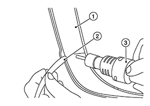
Procedure Overview
|
1 |
:Plastic welder |
|
2 |
:Filler rod |
|
3 |
:Damaged surface |
A one-sided repair will not be able to totally seal the damage, and would lead to the damage recurring shortly after the repair. This is why both sides of the plastic part must always be welded.
The repair always begins on the inside of the component. The plastic part and the filler material are fused and welded together with a jet of hot air. Several layers of the filler material can be overlapped and welded to each other in the process. A single weld seam is normally sufficient on the outer side.
Any protruding filler material on the outer side of the plastic part is sanded off. The part is then prepared for refinishing.
-
Protect the surrounding area:
Protect the surrounding area next to the damage with masking and/or duct tape.
-
Prepping the area:
Sand the paint off of the surrounding area, on both sides. It is important not to get too much temperature into the area, as this can bring out plastic oil residue. Best is to hand sand at the end as to remove and dirt residue from the surface. You can use either a scraper or sandpaper (80/120 grit).
Repair Steps for Plastic Fusion
For a proper fusion to occur both materials have to be in the melting state. Meaning the welding rod and the material to be welded, each plastic has a different melting temperature as well as its own MFI (Melding flow index). Which means in the production process the melding temperature as well as the pressure gives the material its property. With the Plastic Fusion we are using a high welding temperature and a low air volume. This has the advantage to get a controlled welding bath without deforming the surrounding area. There are three points to consider during the fusion process.
-
Welding bath
-
Welding rod angle
-
Pressure on the rod
The plastic fusion is using a one set temperature of 480 degrease on all plastics no matter what its melting temperature is. The different types of plastics will start to melt at different points and this can be seen in the melting bath. The melting bath can be seen with a small rolled plastic in front of the rod.
During welding, the angle of the filler rod in relation to the repair part should be at less than 90° (acute angle). Slight downward pressure on the filler rod is also important as this will create the right pressure in the weld pool. Without the correct rod angle and pressure, the weld pool will not be created successfully.
-
Welding Rod & Weld
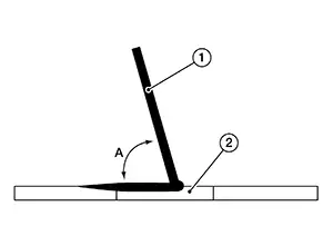
1
:Filler rod
2
:Weld pool
A
:Filler rod angle less than 90°
The right selection of plastic is required. We are using a standard rod which is ideal for the following materials. These are the main plastics used in today’s outer skins of a Nissan Sentra vehicle. There are always exceptions as well as the adhesions to the plastics because of the minor add-on in the materials.
-
PP+E/P
-
PP
-
PP/EPDM
-
P/E
-
TPO
-
TSOP
-
PC
Other rods are needed for the following materials:
-
ABS
-
HDPE
-
PA
-
Xenoy/PC /PTB
-
LDPE
-
PVC
-
Xenoy/PC /PTB
Repairing a Crack or a Cut
-
Grind paint off slowly from both sides. Make sure that the area is clean of any dirt or any other material. Make a slight groove in the damaged area.
Note:
It is important that the outer disc speed is reduced so no melding of the material occurs.
1
:Crack or cut
1
:Grinder
2
:Crack or cut
-
Tack (2) the end of the damaged area (1) in the rear, as this will prevent the damaged area to deform during the fusion process. Try to tack as close to the edge as possible.
-
Start the fusion process in the rear fist. Always start 1cm behind the actual damage.
1
:Crack or cut
2
:Filler rod
3
:Plastic welder 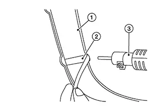
1
:Crack or cut
2
:Filler rod
3
:Plastic welder -
Repeat the process on the front.
Note:
Let the part cool off before you do the finish grinding. As stated before, it is important to grind of the material very slowly. As the high speed will cause the material to meld.
1
:Crack or cut
2
:Plastic welder
3
:Filler rod 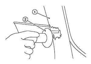
1
:Crack or cut
2
:Grinder
Repairing a broken tab
-
Grind off the paint on both sides. Make a slight groove on the broken edges.
-
Start the fusion process on one side. Make sure that on that side the material is well bonded. Once one side is bonded, let the material cool off and make a bridge. Then first heat the back of the welding strip quickly to be able to bend it. Then weld the other side making sure you get a good bond.
1
:Plastic welder
2
:Filler rod
3
:Broken tab 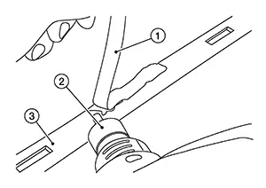
Note:1
:Filler rod
2
:Plastic welder
3
:Broken tab
Once the bridge is bonded use the flat vice grip (1) to smoothen out the area, while it is still warm. Repeat the process on the bottom side.
2
:Broken tab
-
Grind off the non-necessary material slowly as not to melt the material.
Repairing or filling plastic gap
-
Using P120 grit paper, sand down the edges of the break to form a "V" or wedge shape.
1
:Original damaged plastic
2
:Damaged plastic prepped for repair
-
Weld strip on one end.
Note:
Clamp tab while still warm.
1
:Filler material
2
:Original damaged plastic
3
:Plastic welder
-
Lay strip over the gap and continue welding on other side.
Note:
Clamp tab while still warm.
1
:Filler material
2
:Original damaged plastic
3
:Plastic welder
-
Weld new strip on underside.
Note:
Clamp tab while still warm.
1
:Filler material
2
:Plastic welder
3
:Original damaged plastic
-
Change angle of plastic welder (2) and weld both filler materials together.
1
:Filler material
3
:Original damaged plastic
-
Change angle of plastic welder (2) and finish welding on other side.
Note:
Clamp tab while still warm.
1
:Filler material
3
:Original damaged plastic
Other materials:
Front Fender
Exploded View
Exploded View
1.
Cowl top side trim cover
2.
Front fender baffle A
3.
...
Component Parts. Interior Lighting System
Interior Lighting System
Component Parts Location
Component Parts
Location
A.
View of instrument panel
B.
Fuse block (J ...
Front Door Finisher
Exploded View
Exploded View
1.
Front door panel
2.
Front door finisher
3.
...