Nissan Sentra B18 (2020-2025) Service Manual: Body Welding and Precautions
Outline of Welding
Features of Welding
Features of Welding
-
No restrictions on the shape of joint
-
Reduction in weight compared to using of bolts or rivets
-
Great strength
-
Airtight and watertight
-
High working efficiency
-
Some welding processes require higher welding skills.
-
The welded parts can be separated only by breaking the weld. (Except when brazing)
Safety Section
Safety Section
The occupational safety regulations include provisions on preventative measures for avoiding damage and accidents. As the occupational safety regulations are country- specific, this document only lists general information on occupational health and safety for working with steel.
The general, non-material-specific protection and hygiene measures in the workshop must always be observed.
Protective equipment
The following table provides an overview of the general personal protective equipment for material processing:
|
Protective equipment |
MAG welding |
Spot welding |
Sanding / Grinding & Cutting |
|
Protective shoes |
X |
X |
X |
|
Work clothing |
X |
X |
X |
|
Safety goggles |
X |
X |
|
|
Welding gloves |
X |
||
|
General protection gloves |
X |
X |
|
|
General apron |
|||
|
Latex gloves |
|||
|
Fine dust mask |
X |
||
|
Breathing protection with filter* |
|||
|
Ear defenders |
X |
||
|
Welding apron, clothing suitable for welding |
X |
X |
|
|
Welding shield, welding mask |
X |
*only if there is insufficient ventilation
The up-to-date guidelines and notes in the workshop information system ISTA must always be observed. In addition to the general protective equipment, country-specific provisions must also be complied with where applicable.
Working area
A safe and high-quality working environment requires cleanliness and order. When processing steel components, workers must always not only ensure that they themselves are safe, but also that other work bays and employees are not put at risk.
|
Protective equipment |
MAG welding |
Spot Welding |
Sanding / Grinding & Cutting |
Bonding |
|
Partition walls, protective curtains |
X |
X |
X |
|
|
Welding emission extraction |
X |
A fire extinguisher must always be close to hand during work with a raised level of fire risk for example MAG welding.
The up-to-date guidelines and notes in the workshop information system ISTA must always be observed. In addition to the general protective measures for the working area, country- specific provisions must also be complied with where applicable.
Tools
The general and country-specific safety regulations for work with tools for processing metal must be complied with.
The general safety regulations are:
-
Do not clean tools with compressed air.
-
Do not use abrasives that have already been used for processing aluminum.
-
Always separate tools for steel processing and aluminum processing.
Environment
The proper disposal and recycling of materials are described in the environmental protection law. The laws serve to protect natural resources and preserve the environment. Environmental protection laws are regulated on a market-specific basis.
Recycling
Scrap metals from Nissan Sentra vehicles are largely recyclable. The steel is added to the steel production process.
To separate the various materials in the body shell, the body shell is compressed into a bundle and shredded. The shredded material is separated into ferrous metals, non- ferrous metals and other materials. This is done with the sink-float method using their different weights.
Welding of Automobile Body
Welding of Automobile Body
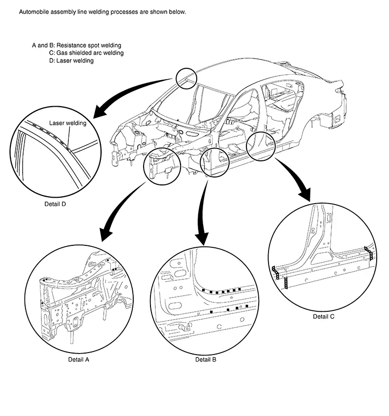
The automobile body is fabricated by welding 0.6 mm - 1.4 mm (0.024 in - 0.055 in) thick sheet steel. Spot welding is most suitable in terms of cost, quality and working efficiency. On the automobile production line, spot welding is widely used, except for some special areas which cannot use this procedure. Today, spot welding is mostly performed by robots.
In addition to spot welding MAG brazing are also used.
Soldering is not used in the automobile production line.
Automobile assembly line welding processes are shown below.
Electric Resistance Spot Welding
Principles of Spot Welding
Principles of Spot Welding
Resistance spot welding is a kind of electric resistance welding. It is classified as pressure welding. Two or three sheets of metal are overlapped and pressed, and current is passed through the mating surfaces. As the current flows, the metals melt due to Joule heat at the mating surfaces and are joined by the pressure.
Features of Spot Welding
Features of Spot Welding
-
Short welding time and high efficiency compared to other welding processes
-
Minimum thermal strain due to partial heating
-
No need to finish the welded surface
-
Less rust formation compared to other welding processes due to application of conductive sealer
-
Great welding skill is not needed. Uniform weld strength can be obtained regardless of worker's skill
-
Heavy welding machine is required to produce high current
-
Most suitable for welding thin sheet metals
-
The condition of the weld is difficult to check from the outside
-
Paint must be removed from the surfaces to be welded
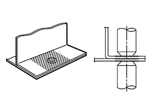
Construction of Spot Welder
Construction of Spot Welder
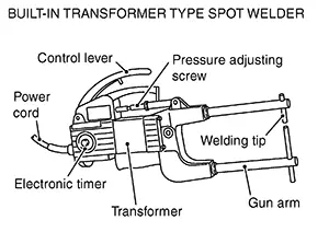
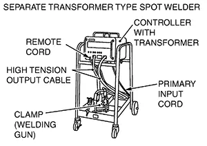
The spot welding machine consists of a transformer unit which supplies the voltage and current required for welding, a timer unit which controls the current passing time, and a welding gun.
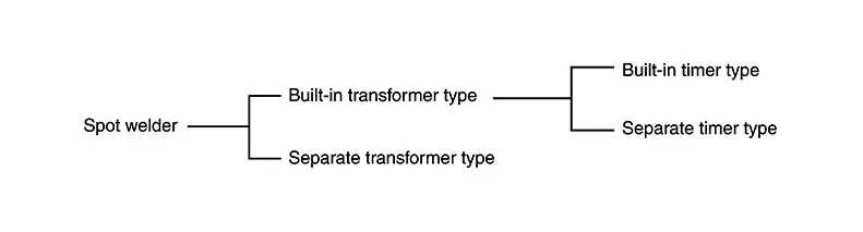
The separate transformer type includes a multi-functional type for welding of pins and washers.
|
|
Cooling Methods
Cooling Methods
-
Air cooling: Forced air cooling with fan
-
Water cooling: Cooling by circulating the water
Spot Welding Gun
Spot Welding Gun
(1) TYPES OF CLAMP
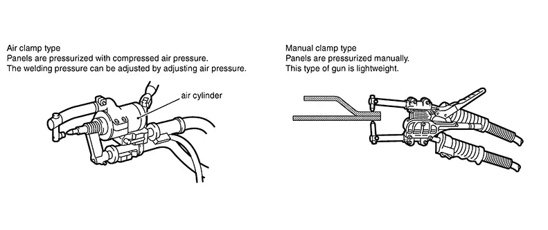 Note:
Note: 
Manual Clamp Type welders donŌĆÖt apply enough pressure.
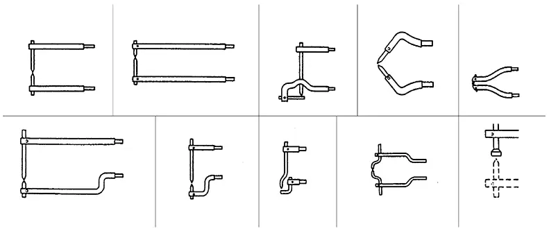
(2) ATTACHMENT ARM
-
In spot welding, 2 or 3 panels to be welded must be clamped directly at electrodes. Therefore, the disadvantage of spot welding is that there are some points at which welding cannot be performed.
-
In order to make up for this weakness, various types of attachment arms have been created.
(3) HANGING UNIT
-
The weight of guns, arms and cables has been reduced to minimize the burden on workers.
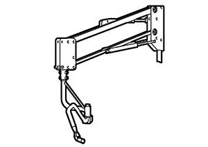
-
Depending on the unit type, the cable can simply be hung, or the gun can be hung with a cylinder.
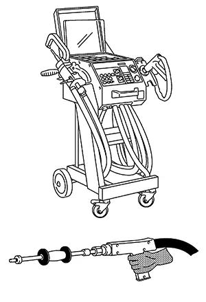
Mult-Functional Type Spot Welder
Mult-functional Type Spot Welder
In addition to the ordinary spot welding function, sheet metal can be pulled with the sliding hammer.
Major functions:
-
Both sided spot welding
-
One sided spot welding (Pre tack welding)
-
Spot hammer welding
-
Nuts and bolts welding
-
Carbon shrinking
-
Contact shrinking
-
Washer and pin or stud welding
Process of Spot Welding
Process of Spot Welding
It takes 3 processes, ŌĆ£pressurizationŌĆØ, ŌĆ£energizationŌĆØ, and ŌĆ£retentionŌĆØ, to complete the spot welding.
(1) PRESSURIZATION
-
The welding points of overlapped panels are pressurized with the tip (electrode) for close contact.
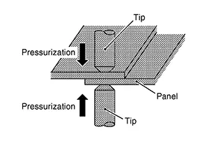
-
With the panels contacting closely, the current can run intensively.
(2) ENERGIZATION
-
With the panels being pressurized, heavy current is applied.
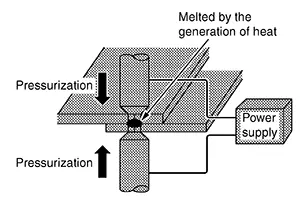
-
Joule heat is generated at panel mating areas, and the temperature rises sharply.
-
The panel mating areas are melted and fused together by welding pressure.
(3) RETENTION
-
Even after the current is turned off, pressure is still applied until the welded point cools down.
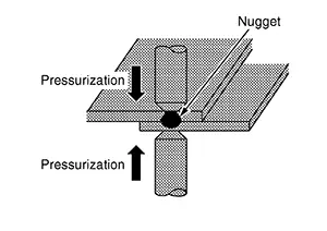
-
The nugget system becomes delicate by pressurization, resulting in better mechanical properties.
-
Therefore, the retention process must not be omitted.
Condition of the Panel
Condition of the Panel
Before beginning, thoroughly check the panel and make any necessary corrections.
(1) CLEARANCE BETWEEN WELDING SURFACES
Gaps between the surfaces to be welded cause poor current flow. Even if welding could be done without removing such gaps, the welded area would be smaller, resulting in poor strength.
Flatten the two surfaces to remove the gaps, and clamp them tightly before welding.
Assessment of spot-weld areas
Before body components are actually joined, it must be ensured that every welding surface to be joined meets the strength requirements and is adequate for the accident safety resulting from these. To this end, test welds can be made on offcuts of the replacement part that are not required. The results of the welding can also be used for fine adjustment of the spot-welding apparatus, if necessary.
|
Weld |
Feature |
Explanation |
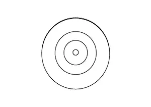 |
Welding spot OK |
|
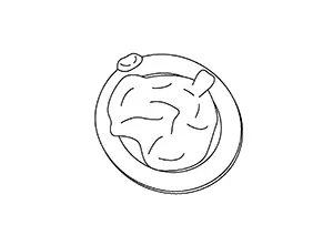 |
Weld penetration too deep, heat affected zone too great |
Excessive build-up of heat due to raised welding current or excessive welding time. |
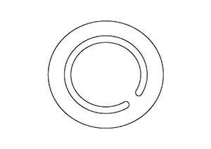 |
Misshapen contact point |
Contaminated electrode tip. The distorted resistance measurement caused by this leads to incorrect welding parameters and, as a result, to reduced connection strength. |
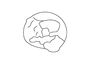 |
Surface damage |
Excessive contact resistance due to insufficient contact pressure electrodes. |
In addition to the visual assessment of the welding spots, a peel test must also be performed. To do this, the metal sheets that were previously joined with a welding spot are separated by peeling. During this test the welding spot must be pulled out of one of the two metal sheets completely. The size of the welding spot must have a certain minimum diameter.
├ś nugget > 4 x ŌłÜ sheet thickness (thinnest sheet of connection). An approximate value for the diameter of the peel test can be found in the following table.
|
Sheet thickness in mm |
0.8 |
1.0 |
1.2 |
1.6 |
|
Diameter of weld nugget in mm |
3.6 |
4.0 |
4.4 |
5.0 |
(2) PANEL SURFACES TO BE WELDED
Paint, rust, dust, or any other contamination on the panel surfaces to be welded cause insufficient current flow and poor results.
Remove such foreign matter from the surfaces to be welded by sanding or wiping clean.
(3) CORROSION PREVENTS PROPER WELDING OF PANEL SURFACES.
Coat the surfaces to be welded with an anticorrosion agent that has high conductivity.
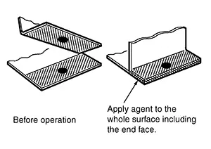
It is important to evenly apply the agent to the panel including the end face.
Perform the spot welding before the anticorrosion agent gets dry, as the agent has generally low conductivity.
Because the wet agent can move from the welding portion due to the welding pressure, that leads to the good quality of spot welding by high conductivity.
Precautions When Performing Spot Welding
Precautions when Performing Spot Welding
(1) SELECTION OF SPOT WELDING MACHINE
Use the direct welding method whenever possible.
(When direct welding cannot be applied, use MAG plug welding.)
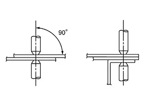
(2) APPLICATION OF ELECTRODE TIPS
Apply electrodes at right angles to the panel. If they are not applied properly, the current density will be low, resulting in poor welding strength.
(3) NUMBER OF SPOT WELDING POINTS
Generally, the capacity of repair shop spot welding machines is smaller than that of factory welding machines. Accordingly, the number of points of spot welding should be increased by 20% - 30% over the spot weld number indicated in the Body Repair Manual.
(4) WELDING CORNERS
Do not weld the curved corner. Welding this portion results in stress concentration, which leads to cracks.
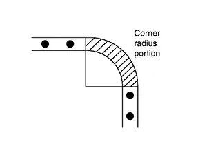
Examples:
-
Upper corner of front and center pillars
-
Front upper portion of rear fender
-
Corner portion of front and rear windows
(5) MINIMUM WELDING PITCH
The minimum welding pitch varies with the thickness of panels to be welded. In general, observe the values in the following table.
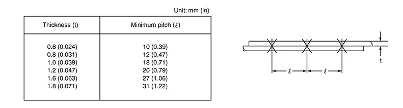 Note:
Note:
The excessively small pitch allows the current to flow through surrounding portions, resulting in poor welding strength.
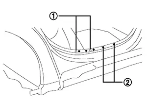
Avoid welding over previously welded areas.
As spot welded portion will become harder and thinner, the different portion should be welded as possible.
|
|
Old Spot Locations |
|
|
New Spot Locations |


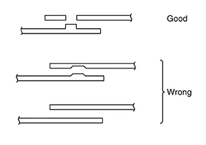
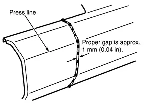
(6) MINIMUM LAP OF PANELS
Observe the following values for the lap distance of panels. Too short of a lap distance results in reduced strength and also in a strained panel.
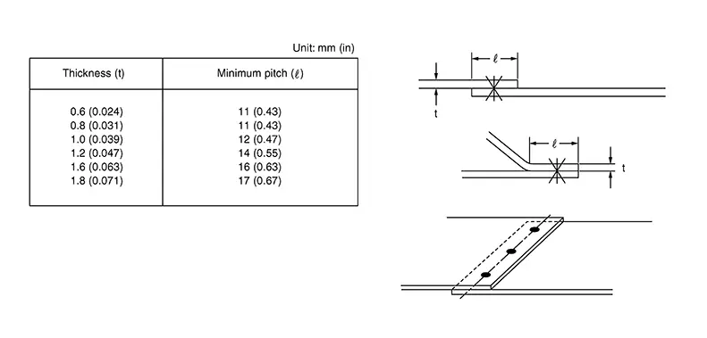 Note:
Note:
Be sure to spot weld at the center of the overlapped portion.
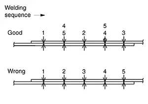
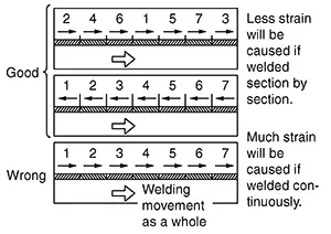
(7) SPOTTING SEQUENCE
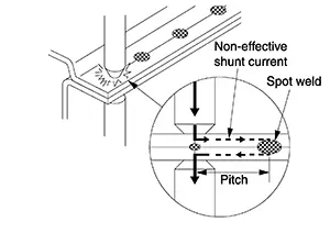
Do not spot weld continuously in one direction only. This causes weak welding due to the shunt effect of the current. If the welding tips become red-hot, stop welding and cool the tips.
Inspection of Welded Portion
Inspection of Welded Portion
Spot welded portions can be checked by the destructive inspections explained below. They can be easily adopted when welding. Before and after welding, you should perform these destructive inspections to check the strength of the welded portions.
The welding spots should be equally spaced and arranged at the center of the flange to be welded.
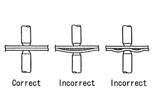
(1) CHECK BY USING TEST PIECE (Confirmation before operation)
Note:
Clamp both test pieces together so that they will not slip or move during welding.
(a) Weld together test pieces with the same thickness as the panel to be welded.
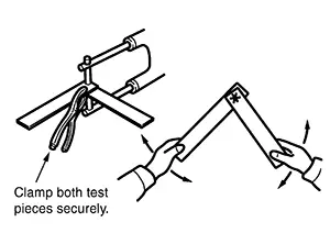
Break the weld by twisting, and examine the break.
(b) With this test, a hole should be made on one test piece by tearing at the welded portion. If no hole is formed, it indicates that the welding conditions are incorrect. Adjust the pressure, welding current, current passing time and other conditions, and repeat test until the best result is obtained.
(2) CHECK BY USING CHISEL AND HAMMER (Confirmation after welding)
(a) Insert a chisel tip between the welded panels, and tap the end until a clearance 3 mm - 4 mm (0.12 in - 0.16 in) [when the panel thickness is 0.8 mm - 1.0 mm (0.031 in - 0.039 in)] is formed between the panels. If the welded portions do not separate, it indicates that the welding has been done properly.
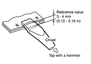
This clearance varies with the location of the welded spots, length of the flange, panel thickness, welding pitch, and other factors. Note that the value shown above is only for reference.
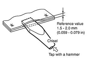
(b) If the thickness of the panels is different, the clearance must be limited to 1.5 mm - 2.0 mm (0.059 in - 0.079 in). Further opening of the panels can become a destructive test.
(c) Be sure to repair the deformed portion of the panel after inspection.
Mag Welding
Mag Welding
MAG Welding
MAG welding uses the heat of an electric arc to join two pieces of metal by fusing both the metal and the electrode. For auto repair MAG (Metal Active Gas) are the types of arc welding most often used.
Principles of Mag Welding
Principles of MAG Welding
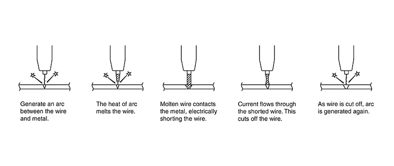
The welding electrode consists of a wire wound on a reel. This welding wire is fed by an electronically controlled motor.
The welding zone is shielded from the atmosphere by injecting a shielding gas. This prevents oxidation and nitriding so that greater weld strength and a good weld bead can be obtained. The shielding gas is argon, CO2, or a mixture of both.
The following figure shows the welding procedure.
Features of Mag Welding
Features of MAG Welding
-
Less slag
-
Less thermal strain
-
Comparatively easy to master
-
Greater weld strength than gas or spot welding
-
Suitable for thin sheet metal
-
Less influence of welding position to the strength of weld
-
Not suitable for windy locations
Structure of Mag Welding Machine
Structure of MAG Welding Machine
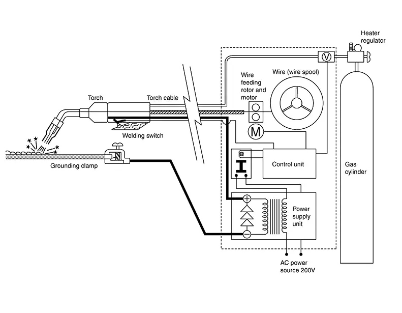
The welding machine consists of a power supply unit composed of a transformer and rectifier which converts the source voltage to welding voltage and rectifies the current. A controller which controls the voltage, current and welding wire feed speed corresponding to the thickness of the welding panel. Welding wire which is wound around the wire spool, wire feed motor, welding torch, gas cylinder, and regulator.
Condition of Panel to Be Welded
Condition of Panel to be Welded
Paint, rust, or oils on the surface of the panel cause blowholes and spatter when the panel is welded. Thoroughly remove any foreign matter with a belt sander or wire brush.
Inspection of Welded Portions
Inspection of Welded Portions
Refer to the inspection method for spot welding. Refer to Inspection of Welded Portion.
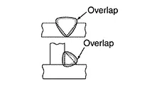
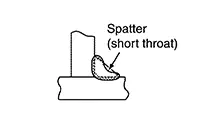
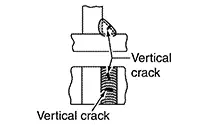
Sample defects and welding conditions of MAG welding.
|
Defect |
Check points |
Remarks |
|---|---|---|
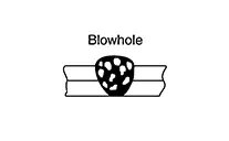 |
|
A hole is made when gas is trapped in the weld metal. |
 |
|
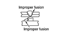
This is an unfused condition between weld metals or between deposited metals. |
 |
|
|
 |
|
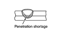
This is a condition where there is poor deposition made under the panel. |
 |
|
|
 |
|
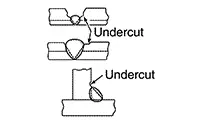
Spatter is prone to occur in fillet weld. |
 |
Are there any stains on welded surface (paint, oil, rust)? |
Cracks usually occur on top surface only. |
Types of Mag Welding
Types of MAG Welding
Welding Methods Using Gas Shielded Arc Welding
Note:
Before MAG welding is performed on body components, some test welds should be carried out on offcuts of the replacement part that are not being used. When doing so, the welder settings can be optimized for the relevant material. The table shows some typical fault patterns and the relevant remedial measures.
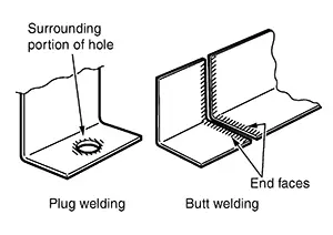
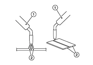
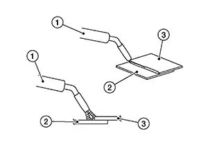
Butt welding
The welding method that plugs the gap between two panels put together side-by-side. This method is used in welding for areas such as cut & joined areas on Quarter Panels and Rocker Panels. The finishing work is conducted the same as for plug welding.
|
1 |
:Torch |
|
2 |
:Panel |
Fillet welding
The welding method where two panels are overlapped and the edge of one side is welded to join them together. Mainly being utilized in welding on frame type Nissan Sentra vehicles.
|
1 |
:Torch |
|
2 |
:Panel 1 |
|
3 |
:Panel 2 |
Continuous welding
This welding process is suitable for sheet steel 2 mm (0.08 in) thick or over. If applied to thinner panels, it will cause melt-through.
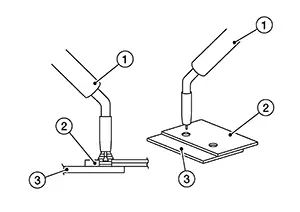
Plug welding
Apply the torch at a right angle to the panel and quickly fill the hole with the molten metal intermittent welding generates oxide film, causing blowholes. When plug welding make a hole 5 mm - 6 mm (0.20 in - 0.24 in) in diameter in the upper of the two panels to be welded. Keep the upper panel and lower panel tightly together. For the finishing work, the raised welded area is smoothed out using a tool such as a belt sander.
|
1 |
:Torch |
|
2 |
:Panel 1 |
|
3 |
:Panel 2 |
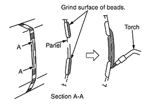
Intermittent (step) welding
This method is suitable for thin or rusted panels to prevent thermal deformation and melt-through. In body repair, it is used as butt welding on partial panel replacements.
Before step welding, tack weld the panels to be welded to prevent strain and to align panel surfaces.
-
To do this, point weld and then fill in the spaces with short welding beads.
-
Remove all coatings from the replacement and joining panels within 1/2 inch (13mm) of the weld joint. This must be done on both the front and back side of the panels to prevent burnt coatings from interfering with corrosion protection later in the repair process.
-
Long weld line will cause strain. Use the method as shown in the figure to reduce strain.
-
To fill the spaces between intermittently placed beads (A), grind the beads using a sander, then fill with molten metal. If this is done without grinding the surface of the beads, blowholes may result.
Separation process
Separating cuts on steel body components can be made with a body saw or an angle grinder with cutting disc. This should be done with a body saw if possible as angle grinders produce a large amount of sparks and the material may overheat at the cutting edges. It is essential to use a body saw when repairing the outer body skin for example partial replacement of a side panel. Sanding belts may also considered in some areas.
The blades of body saws, however, are only suitable up to a certain strength and material thickness. Separating cuts on body structure components made of high- strength or ultra-high-strength steels can only be made using an angle grinder with a cutting disc.
Opening spot-weld areas
To open spot-weld areas, the original welding spots are drilled out with a weld spot drill bit. A special weld spot drill bit with a controllable cutting depth must be used for this. This prevents the tool from drilling through the second sheet of metal. The sheet metal flanges are then separated from each other with a chisel.
-
Surface-grind the surface if necessary
-
Centre the punch mark on the welding spot
-
Drill out the welding spot
The heat during welding sometimes causes the surface of the welding spot to harden. In such cases, the welding spot must be sanded again before being drilled out. A belt sander can be used for this. Special welding spot cutters are required to loosen spot-weld areas on high-strength and ultra-high strength steels. Conventional weld spot drill bits are destroyed by use on high-strength and ultra high-strength steels. Alternatively, the welding spots can also be completely sanded down with a belt sander. When doing so, it must be ensured that the component underneath is not damaged.
Opening MAG weld seams and MIG soldered seams
MAG weld seams and MIG soldered seams are opened by being ground/sanded out with an angle grinder or belt sander. The remaining components must not be damaged during this process. The sheet metal flanges are then separated with a chisel. The procedure for high-strength and ultra-high-strength steels does not differ here from the procedure for steels with low strength. However, the abrasives are subject to significantly higher wear. Opening laser weld seams Laser weld seams are opened with an angle grinder. To do this, the laser weld seam is ground through together with the top metal sheet. It is essential to prevent damage to the metal sheet underneath during this process.
Other materials:
B1383 Incomp Steering Angle Sensor Adjust
Dtc Description
DTC Description
DTC DETECTION LOGIC
DTC No.
CONSULT screen terms
(Trouble diagnosis
content)
DTC detection condition
...
Parking Brake System. Foot Pedal
Precaution. Precautions
Precautions
Precaution for Supplemental Restraint System (srs) "air Bag" and "seat Belt Pre-Tensioner"
Precaution for Supplemental Restraint System (SRS) "AIR BAG" and "SEAT BELT PRE-TENSIONER"
The Supplemental Restraint System such as
ŌĆ£AIR BAGŌĆØ and ŌĆ£SEAT BEL ...
Precaution. Precautions
Precautions
Precaution for Supplemental Restraint System (srs) "air Bag" and "seat Belt Pre-Tensioner"
Precaution for Supplemental Restraint System (SRS) "AIR BAG" and "SEAT BELT PRE-TENSIONER"
The Supplemental Restraint System such as
ŌĆ£AIR BAGŌĆØ and ŌĆ£SEAT BELT PRE-TENSIONERŌĆØ,
u ...