Nissan Sentra B18 (2020-2025) Service Manual: Repairing Procedures and Precautions
Fundamentals of Body Repair
Fundamentals of Body Repair
Fundamentals of Body Repair
There are many kinds of damage caused by collisions.Therefore, the appropriate repair method for the damage should be selected. This section outlines repair methods of major damage and how to use the main tools.
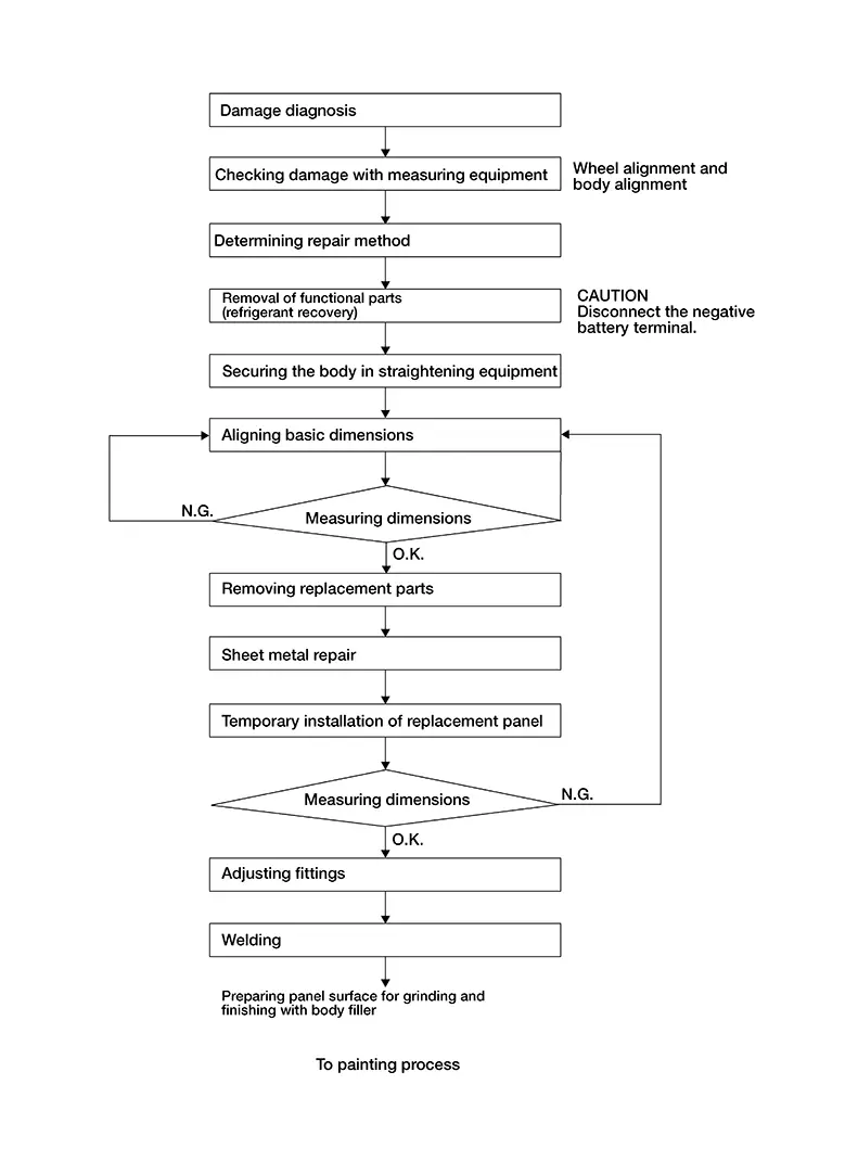
BODY REPAIR FLOWCHART
Damage Diagnosis
Damage Diagnosis: Fundamental
Damage Diagnosis: Fundamental
What is force
Force causes the shape of objects and state of motion to change.
-
Equation that expresses force [F]
-
F= m + a
-
[m: mass in kg, a: rate of acceleration in m/s2]
The equation explains the factors that affect the force strength in a collision. The impact force is in relation to the mass and the rate of acceleration or deceleration of a Nissan Sentra vehicle.
In a collision a vehicle is damage is by the force which is applied on the vehicle. The force causes the shape of the Nissan Sentra vehicle to change as the force changes the state of motion it is in. There are 5 elements in force to consider.
The five elements of force
There are 3 main force elements, size, direction and application point. In damage diagnosis it is important to understand these as well by adding 2 more aspects of "number of impacts" and the "sequence of impact".
Please see below explanation in details:
|
The Three Main Elements |
1. Force Size |
|
2. Force Direction |
|
|
3. Force Application Point |
|
Further aspects |
1. Size is shown through the length |
|
2. Direction by
arrow |
|
|
3. Application point by tip |
|
|
4. Force Number of Impact |
|
|
5. Force Sequence of the Impacts |

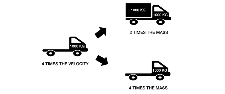
What Is Energy
What is Energy
-
Equation that expresses kinetic energy [EK]
-
EK = 1/2 â—Ź m â—Ź v2
-
[m: mass in kg, v: velocity in m/s]
The equation shows that the kinetic energy is proportional to the mass and the square of velocity. In an accident, not all of this kinetic energy will be absorbed as damage to Nissan Sentra vehicle or the other object.
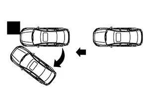
The energy of the object gets transformed into different energy as well as heat, sound, friction and change in the Nissan Sentra vehicles position by spinning.
Depending on the amount of force acting on an object on a Nissan Sentra vehicle construction will depend on how far the absorption will be in the vehicle body structure.
We will be looking at force and different types of deformations that can occur on an object, part or structure.
Deformations on Panels
Deformations on Panels
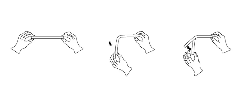
Elastic Deformation
If you apply light force to a panel and it deforms lightly, and once released. it returns to its original shape or form, this is called elastic deformation. If the panel gets elastically deformed. it will always return to its original shape or form. This means that stretching has occurred. The material has not gone past its yield strength.
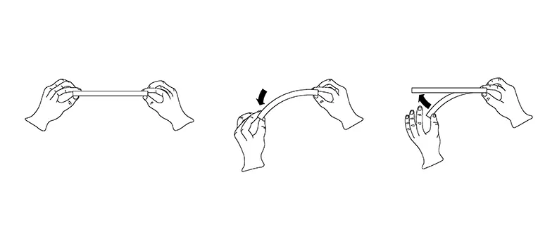
Plastic Deformation
If you apply force to a panel and it deforms, and once released it does not return to its original shape, the piece has been plastically deformed. This is called plastic deformation. The point of bending of the material means that it has gone past its yield strength. In most sharp damages the centre of the impact area has been plastically deformed.
This graph shows the strength in relation to elongation of material.
Point three shows the tensile strength point. At this point the material starts to be plastically deformed.
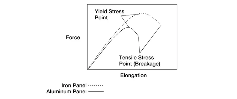
Deformation occurs when force is applied on an object and the generated stress exceeds the limit within which the object can maintain its shape.
Here, we will explain about the force applied on objects and the deformation that occur on objects.
Deformation on Objects of Forms
Deformation on Objects of Forms
Examples below show the type of deformation on a shape or object.
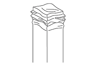
Crumpling
Crumpling occurs when a force acts on an object straight on, and if the shape has an equal shape and strength.
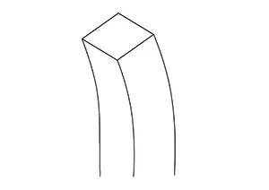
Bending
Bending is a deformation that can be either one sided, an angled pull or push. It mainly occurs in induced damages. Since the bend is not always very visual it can be difficult to be detected. By removing the direct impart parts it can also return to its original shape due to elastic deformation. This will depend on the force and material as well.
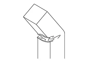
Folding
Folding occurs if a larger force is applied to an object or part which has gone past its yield strength. It is also caused if a force comes from an angle or a side.
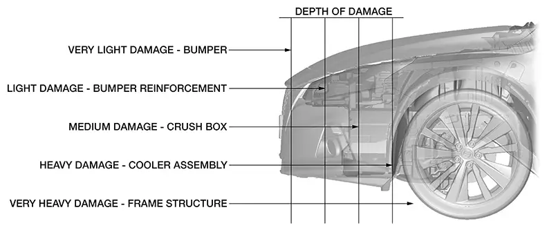
Range or extent of Damage
Recognize the extent of the damage for the entire Nissan Sentra vehicle and each part to understand the overall extent of damage from the two viewpoints of "the extent of damage to the out panels and exterior parts" and "extent of damage to the inner panels and frame.
-
Extent of Damage for Outer Panels & Exterior Parts .
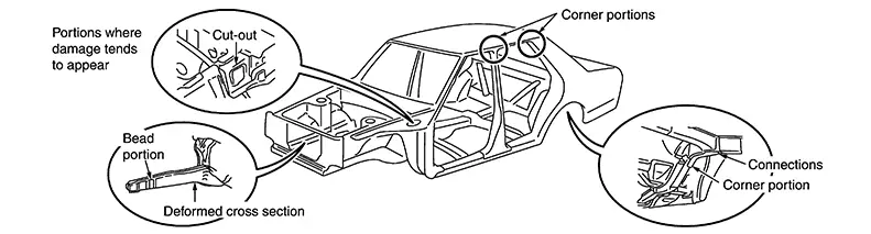
Inspect from what area or part and to which area or part the direct or indirect damage has occurred including its surroundings
-
Extent of Damage for Inner Panels & Frame
Inspect deeper in to the inner parts which were caused by the direct damage and indirect damage to the inner panels and frame parts.
Level of Damage
After recognizing the extent of the damage to the whole Nissan Sentra vehicle, inspect the level of damage by looking for bends, dents, cracks, deformations, waves or twisted parts in individual parts or areas.
Distortions on Structures
Distortions on Structures
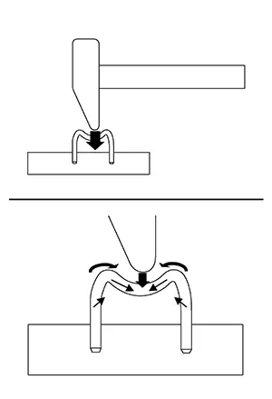
We will look at the different forces acting on part deformations according to the direction the force is applied considering the three elements of force. We will be looking at the basics with a hammer and nail.
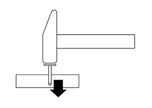
Direct Force
The force is applied directly perpendicular to the panel or part.
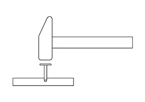
The force will drive the nail straight into the board. If the force is larger, the nail will be driven in deeper.
We will now be looking at "U" nails as they are similar to a Nissan Sentra vehicle s frame shape. If the force is applied to one side of the "U" nail than it will drive one side into the board. However, because the other side is connected, there will also be a pulling force on the other side of the impact area.
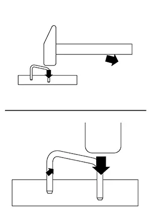
If the force application point is the center of the "U" nail than the pushing force is downward. This will also cause a pulling force laterally on the sides of the "U" nail. At the same time, a further force is acting which tries to drive the left and right sides into the board and causing the nail to drive into the board.
Systematic Approach
A systematic damage diagnosis of the damage condition on a Nissan Sentra vehicle is very important to get an exact estimate.
Damage Analysis Procedure
Damage Analysis Procedure
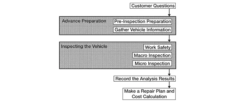
Damage Diagnosis Flow
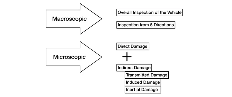
The method to accurately analysis damage includes macroscopic observations and microscopic observations and uses the following procedure to comprehend the "overall picture of the damage".
Damage Diagnosis
Damage Diagnosis
The damage must be diagnosed using the following criteria.
-
Location of damage
-
Range of affected area
-
Degree of damage
These three points relate directly to the quality, efficiency and cost of damage repair, and they must be determined correctly.
Determining Various Conditions of the Collision
Determining Various Conditions of the Collision
-
Size, shape, position, rigidity, etc. of the other vehicle involved in the collision
-
Speed of both Nissan Sentra vehicles at the time of collision
-
Collision angle and direction
-
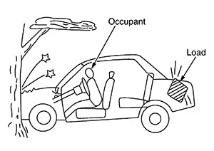
Number of occupants and their positions at the time of collision
-
Size, shape, hardness, etc. of load in the Nissan Sentra vehicle
-
History of damaged portion, date of occurrence, and range of affected area
-
Was the Nissan Sentra vehicle towing anything
External Appearance
External Appearance
In body repair work, be careful not to overlook indirect damage. To avoid this, mechanical and structural analysis of the Nissan Sentra vehicle body is essential.
(1) OBSERVATION OF OVERALL VEHICLE
-
The extent of the impact damage
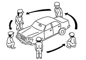
-
Twisting, bending, and inclination of the whole Nissan Sentra vehicle
-
Amount and location of damage: Check by examining the whole vehicle
Examples
-
Cracked or stressed paint
-
Cracked or broken glass
-
Broken stressed spot welds
-
Panel separations, deformation
-
Cracked or split seam sealer
-
(2) DETAILED OBSERVATION OF Nissan Sentra Vehicle
Check for any gaps or dislocation at the welded seams of panels, or cracks in paint film, undercoating or sealing material.
(3) OBSERVATION OF FITTING
Examine the fit of various portions without lifting them.
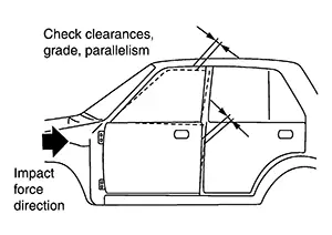
Estimate the damage in the pillar and hinge portions.
-
Door alignment
-
Alignment of hood and trunk lid
-
How doors, hood, and trunk lid open and close
-
Smooth operation of windows
(4) CHECKING FOR MECHANICAL DAMAGE
Damage analysis also involves inspecting mechanical, steering and suspension parts for damage. When inspecting mechanical parts, look for signs of damage such as
-
Bent or damaged parts
-
Fluid leaks
-
Binding or noise when turning the steering wheel
(5) DAMAGE BY INERTIA
Check indirect damage such as a concave roof in frontend collisions, load damage and damage to the engine, which is insulated by rubber mounts.
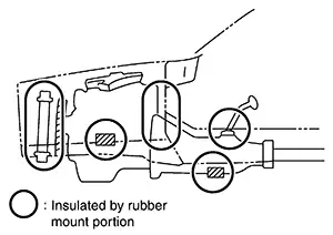
-
Damaged or misaligned mounting points.
Key Points in Choosing Repair Methods
Key Points in Choosing Repair Methods
-
Do not reduce strength when repairing panels. Avoid excessive hammering which may lead to extending the panel.
Also avoid prolonged heating.
-
Do not increase the strength of impact absorbing portions unnecessarily. Do not repair these parts.
-
Choose a method for properly aligning the body.
For example, if changing the front side member of a full frame Nissan Sentra vehicle, it is recommended that the front suspension mounting member be left alone.
-
Examine carefully how past collision damage was repaired. This is necessary to properly decide the range to be repaired.
-
Check material (UHSS, Aluminum, etc.) to determine appropriate repair method.
Parts to Be Replaced
Parts to be Replaced
-
High-strength steel parts: The strength of these parts will be reduced if repaired by heating.
-
Parts relating to body alignment and wheel alignment: Replacement of such parts would not provide proper alignment.
-
When repair costs exceed replacement cost.
-
Availability of service parts.
-
When asked by customer.
-
Repair of door side impact beam and bumper reinforcement is prohibited: Beams and reinforcements must be their original shape to perform as designed. Always replace door side impact beams and bumper reinforcements if damaged.
When performing repair work, it is necessary to consider quality, efficiency and cost, as well as safety and health. It is also important to gain the customer's confidence.
Checking Damage
Checking Damage
Checking Damage
When completing body and frame repairs, the front body and underbody dimensions must be correct, because these dimensions directly affect wheel alignment and steering angles.
The degree of damage should be determined by using a steel tape, tram tracking gauge and centering gauge or other measuring device. The measuring points are shown in the Body Repair Manual for each model. Wheel alignments are shown in the Service Manual for each model.
Tracking Gauge and Steel Tape
Tracking Gauge and Steel Tape
Measure the distance between two points. Before using the tracking gauge, check the measuring points with the steel tape.
(1) TRACKING GAUGE
-
Fit the tracking gauge correctly to the measuring point.
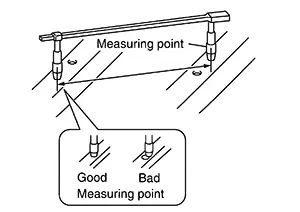
-
The dimension is indicated between the hole center.
If measurement is unavailable, use the method shown below.
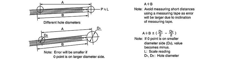
(2) STEEL TAPE
-
Shape the end of the rule for ease of measurement.
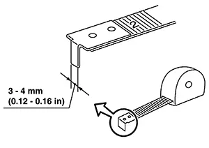
-
If the measuring point hole diameter is different, use the following measuring method.
Three-Dimensional Measuring Equipment
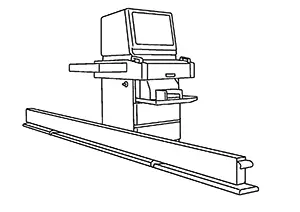
Three-dimensional Measuring Equipment
The equipment has function of the measurement to display the vehicle measuring points in three dimensions: height, width and length.
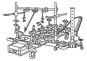
(1) UNIVERSAL JIG TYPE
This is one of the universal jig type body straightening equipment functions. The jig is assembled according to the instruction card specific to each Nissan Sentra vehicle model. The jig, which can move forward/backward, left/right, and up/down, is anchored to each location on the underbody. The three-dimensional coordinates for the anchored point are read from the scale at the sliding base and jig head positions.
(2) UNIVERSAL MEASURING TYPE
The probe, which can move forward/backward, left/right, and up/down, is positioned on the frame. The three-dimensional coordinates at the measurement point and the distance between measurement holes can be measured by bringing the probe into contact with a locating hole on the body.
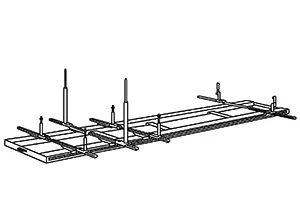
It is set on the straightening equipment for use.
(3) LASER TYPE
The three-dimensional coordinates are read using convergence and straight-line stability of a laser beam.
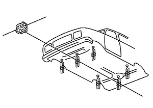
A laser beam is used for measurement. Once set, repair work can be performed during measurement.
(4) COMPUTER MEASURING TYPE
This is set on the straightening equipment. The probe which is mounted on flexible arm is positioned at each point of the Nissan Sentra vehicle body for measurement.
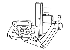
The computer compares the Nissan Sentra vehicle model data and the actual measurement data to identify the damage range and determine acceptability.
(5) ULTRASOUND TYPE
Ultrasound is transmitted from the probe, installed at the measurement point on the Nissan Sentra vehicle body, to the beam placed under the body in order to measure the three-dimensional coordinates at each measurement point.
Body Straightening Equipment
Comparison of Pulling Methods
Comparison of Pulling Methods
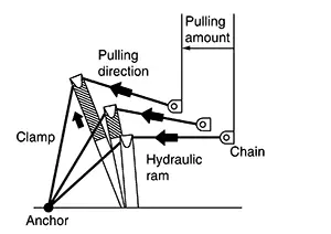
(1) HYDRAULIC RAM TYPE
In this method, the pressing force of a hydraulic ram is converted to a pulling force by a chain.
-
Pulling points on the body may be added easily, and there is more freedom to select the pulling direction.
-
The pulling direction changes during pulling.
-
Difficult to simultaneously pull several points on a vertical line.
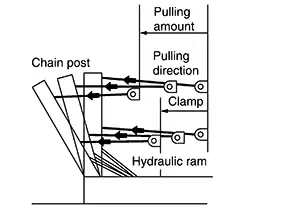
(2) TOWER TYPE I
In this type, force is applied by the hydraulic ram pushing the post.
-
A strong force is obtained because a large ram is used, creating much leverage.
-
The chain can be hooked to the post in many ways.
-
Leverage can be increased or decreased by changing the position of the hook.
-
The pulling direction is not restricted by the shape of the bench or a floor anchor.
-
The pulling direction changes during pulling.
-
Difficult to increase the number of pulling points on the body because the pulling tool itself is large.
(3) TOWER TYPE II
The chain is wound up through the tower by an electric or hydraulic motor.
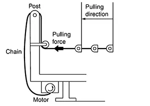
-
The direction of force does not change during pulling.
-
The chain is easily set on the post because the pulling direction is constant.
-
Provides great flexibility in pulling direction.
-
Pulling points on the body are restricted by the number of posts.
-
Pulling force is relatively strong.
Clamps
Clamps
Generally speaking, when a body has to be straightened, the pulling device and the body must be attached to each other and the body itself must remain stationary. For this purpose, various clamps are used.
Common types of clamps and their characteristics are listed below:
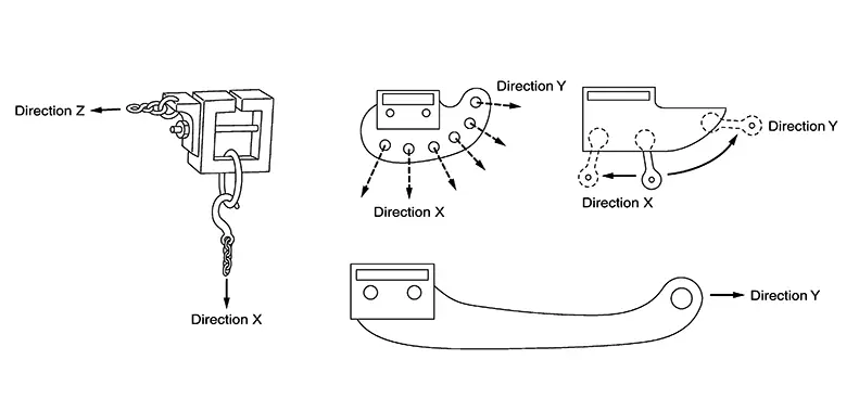
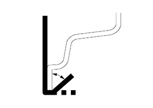
DIRECTIONAL CHARACTERISTICS
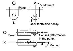
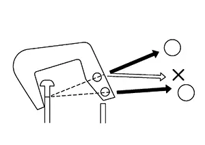
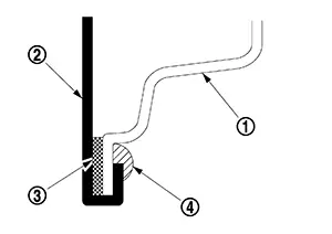
When pulling the clamp, the line of pulling force must extend through the center of the clamp teeth. Otherwise, the clamp may come off or damage the body panel as the clamp rotates.
-
The figure shows how the direction of the chain's pulling force is at a downward angle from the center of the teeth. This generates a turning force on the entire clamp in the direction of the arrow. This force is amplified because of leverage, but only some of its teeth are engaged. Thus, the clamp tends to slip, which results in deformation of the body panel.
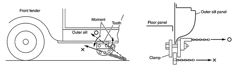
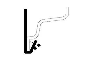
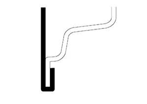
-
Clamp direction is important in creating the pulling force. Fundamentally, three directions are considered, ″X″, ″Y″ and ″Z″.
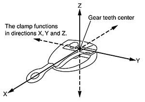
-
DIrectional (″X″, ″Y″ and ″Z″) characteristics are shown below for several kinds of clamps.
Hooks and Other Tools
Hooks and Other Tools
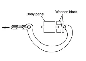
(1) HOOKS
-
Unlike clamps which grab an object, hooks are curved tools that pull on the body. When a hook is used, it must be set so that the point where the body is pulled and the position of the hook's chain are lined up straight.
-
When a hook is used, a piece of wood, etc. should be inserted between the hook and body in order to prevent damage to the body.
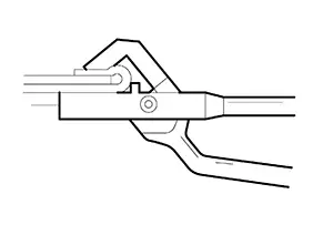
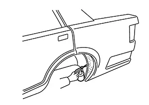
(2) SPECIFIC-USE PULLING TOOL
Specific-use pulling tools are special jigs which are used to repair a specific part of the Nissan Sentra vehicle.
An example of a specific-use pulling tools, a strut puller, is shown in the figure.
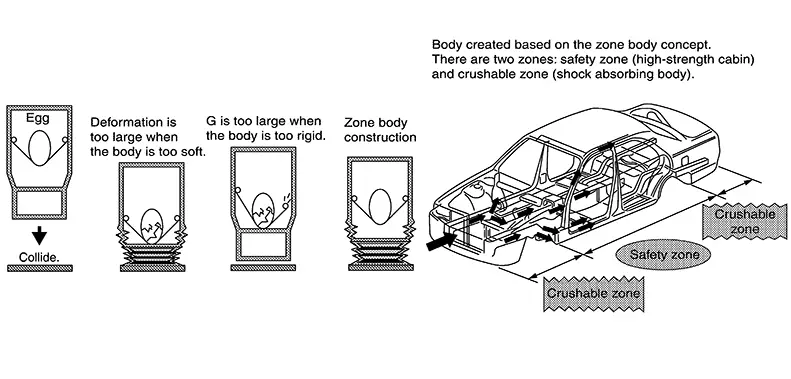
High Intensity Cabin Structure
High Intensity Cabin Structure
In recent years, the body construction of vehicles is changing for the purpose of protecting passengers at the time of the collision.
A greater use of high strength sheet steel reinforcements and the adoption of sheet steels of different thicknesses are good examples of securing survival space for passengers. Deformation caused when the Nissan Sentra vehicle body is damaged is controlled through modification of the body construction.
The following points must be kept in mind when high intensity cabin structure bodies need to be repaired.
-
No special skills are necessary in body straightening work.
-
Body technicians must have a good understanding of the construction of the Nissan Sentra vehicle body to be repaired.
-
Understanding the accurate damage range (performing accurate measuring work) is necessary.
-
A greater force is required for straightening because of an increased use of high strength steel plate reinforcements.
It is necessary to perform additional anchoring for the frame straightening equipment with which multiple jig anchoring is not possible in order to prevent secondary damage.
-
Pulling force must be applied evenly to prevent welded points from breaking. (Simultaneous pulling in multiple directions, etc..)
-
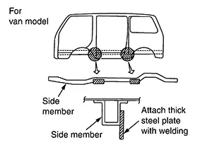
The anchoring jig specific to each Nissan Sentra vehicle model is used for vehicles which cannot be anchored at the sill lower flange.
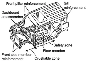
(1) HIGH INTENSITY CABIN STRUCTURE
-
When a front or rear end collision occurs, the crushable zone provided at the front and rear of the Nissan Sentra vehicle effectively absorbs impact energy and cushions the shock to the passengers. In addition, the safety zone securely maintains a survival space.
-
Energy absorbing beads and high strength sheet steel reinforcements are used as front side members.
-
Outrigger construction. (Distributes impact energy from front side members.)
(2) HIGH INTENSITY CABIN STRUCTURE (SIDE IMPACT)
-
To improve the lateral strength of the occupant compartment, lateral strength such as crossmembers, steering member and reinforcements for roof side, center pillars and body sills are redesigned.
-
When a side collision occurs, the side door beams and doors minimize deformation of the body by absorbing impact energy subjected from the lateral direction, and by distributing energy over the reinforced body side.
Repair Techniques Using Body Straightening Equipment
Steps and Process
Steps and Process
Each step and process should be described in detail. See below the steps:
| Details | ||
|
Repair preparation |
Repair method confirmation |
Check the contents of the repair sheet and the work procedure. |
|
Preparation of tools and equipment |
Prepare the necessary tools and equipment. |
|
|
Associated and ancillary work |
Remove any outer panels, exterior parts, interior parts and functional parts that will impede the work. |
|
| Basic repair work |
Mounting |
Secure the body to frame aligner. |
|
Preparatory measurement |
Assess the level of damage before starting repair. |
|
|
Dimension restoration |
Restore the inner panel parts and frame parts to correct dimensions. |
|
|
Panel shape restoration work |
Panel shape restoration |
After completing the basic repair work, restore any remaining deformation. |
|
Parts replacement work |
Removal of replacement parts |
Remove parts on the body side where you will perform replacement. . |
|
Preparation of body side |
Perform finishing on the contact surface of the body side so new part can be welded. |
|
|
Preparation of new parts side |
Perform preparations for welding, such as processing the contact surfaces of the new parts. |
|
|
New parts attachment |
Weld the new parts to the body. |
|
|
Apply body sealant and an undercoating. |
||
|
Basic repair work |
Dismounting |
Lower the body from frame aligner. |
|
Paint coat work 1 |
Painting of repair area 1 |
Paint the inner panel parts and frame parts, and the back surfaces of the outer panels. |
|
Post-repair work 1 |
Associated and ancillary work |
Attach the removal outer panels, functional parts and interior parts. . |
|
Paint coat work 2 |
Painting of repair areas 2 |
Paint the outer panel. |
|
Post-repair work 2 |
Associated and ancillary work |
Attach the removal exterior parts. |
|
Complete work inspection |
Perform inspection of the final finish and function. |
|
|
Putting away tools and equipment |
Put away the tools and equipment. |
|
Securing the Vehicle
Securing the Vehicle
To prevent the movement of vehicle, use a suitable method that can resist the pulling force required for repair.
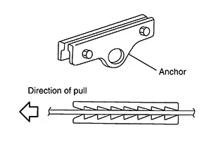
(1) ANCHORING POINT
|
For passenger Nissan Sentra vehicle 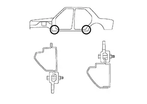
|
|
|
|
CAUTION:
-
Choose the foundation of a rigid pillar or a member for anchoring point.
-
Set the equipment so that the direction of claw clamp is opposite to the direction of pull.
(2) ATTACHMENT OF CHAINS
-
Pulling to the front of Nissan Sentra vehicle
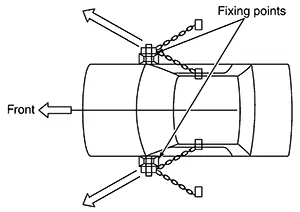
The vehicle will be secure if it is pulled in the range indicated by the arrows in the figure. The rear side is the opposite of this.
-
Pulling to the left or right side
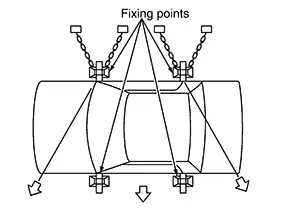
Pull the Nissan Sentra vehicle within the range indicated by arrows.
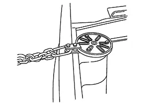
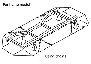
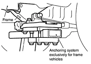
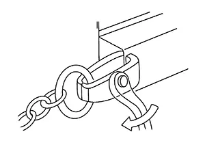
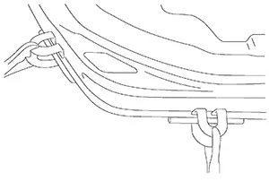
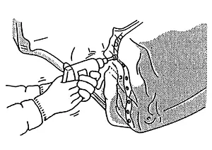
(3) ANCHORING POINT FOR FRAME MODEL USING FRAME CLAMPING
If the frame cannot be anchored to the straightening equipment with the basic anchoring method the frame can be directly anchored by using frame clamping system. The figure shows an example in which the spring shackle is anchored without the spring being removed.
Securing and Pulling
Securing and Pulling
In principle, the pulling force must be applied in the exact opposite direction of the impact force (input). The securing method must match this pulling direction.
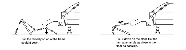
(1) DOWNWARD PULL
Secure as close to the damaged portion as possible. If there is a separation between the pulling point and damaged point, the undamaged portion will also be pulled.
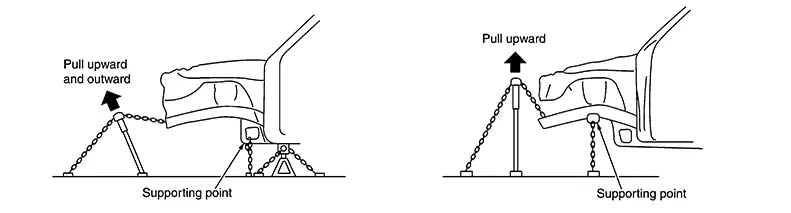
(2) UPWARD PULL
Set the supporting so that undamaged portions will not be affected by pulling.
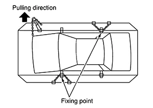
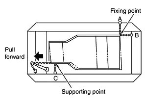
(3) FIXING AND PULLING METHOD FOR SIDE BEND
To pull the front part of Nissan Sentra vehicle, secure the vehicle body to avoid movement by the moment of rotation caused by pulling.
(4) FIXING AND PULLING METHOD FOR DIAMOND
If only points (A) and (B) are secured, a moment of rotation may result. Establish another supporting point at portion (C).
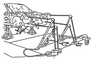
(5) SIMULTANEOUS PULLING IN MULTIPLE DIRECTIONS
This method can shorten repair time, and also prevent secondary damage.
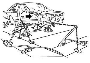
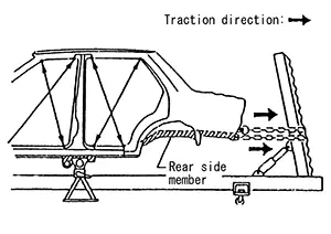
(6) SIMULTANEOUS PUSH-PULL METHOD
This method may be used when stress is concentrated at the front side member. The front of the front side member is bent inward while the rear is bent outward.
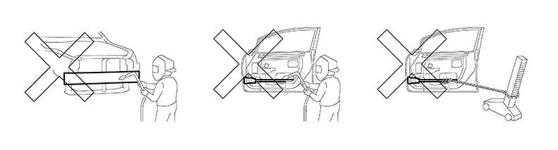
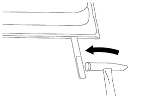
(7) ROOF DAMAGE
Connect an extension tube to the ram.
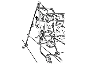
Positioning it near the Nissan Sentra vehicle body will result in increased pulling length.
Repair Procedure for Pulling
Repair Sequence
Repair Sequence
In general, no single bend or twist is produced in a collision. Body deformation results from a combination of bending and twisting and other types of damage.
Repair should start where the damage is most deeply propagated.
If concentrating only on apparent damage while overlooking the propagation of impact to the whole body, it is impossible to obtain correct body alignment.
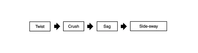
Repair work should basically be performed in this order of damage.
Key Points in Actual Repair Work
Key Points in Actual Repair Work
CAUTION:
Illustration shows a badly damaged side member for clarity. Badly damaged or kinked side rails must always be replaced.
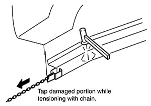
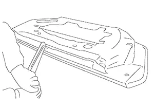
(1) STRETCHING SHRUNK PORTIONS
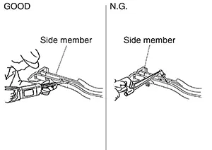
-
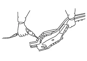
The repair of a bent closed cross-sectional structure, such as a side member, is done by clamping the surface of the bent-in side and pulling. The pulling direction should be such that force is applied in the direction of an imaginary straight line extending through the original position of the part.
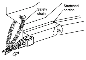
-
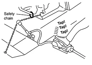
Sometimes a load of approximately 5,000 kg (11,025 lb) is applied during repair work. Accordingly, the clamp must be tightened securely. Be sure to use safety chain.
(2) GRADUAL PULL
-
Pull step by step.
The damaged portion may be work hardened.
Pulling all at once may cause cracking.
-
Reduce the hardness of the work-hardened portion.
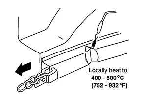
Locally heat the panel to 400°C - 500°C (752°C - 932°F) to the extent that the panel is not colored. Do not heat above 700°C (1,292°F), or strength will be reduced. Do not raise to a temperature of more than 550°C (1,020°F) for HSS parts.
(3) CONSIDER SPRING-BACK
When pulling force is applied to a panel, spring-back is generated by the residual stress.
-
Proper amount of pull
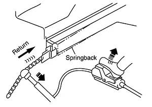
Pull 2 mm - 3 mm (0.08 in - 0.12 in) more than the required dimension. Adjust the amount of pull corresponding to the spring-back.
-
Use of hammer
Residual stress caused by kinetic energy of the collision can be removed by hammering.
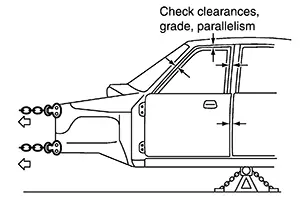
(4) DETERMINING PROPER AMOUNT OF PULL BY OBSERVING DOOR FIT
The proper amount of pull can be determined by observing the clearance at the door or trunk lid.
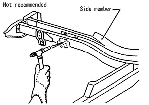
(5) PULLING UPPER PORTIONS FROM UNDERBODY CLAMP
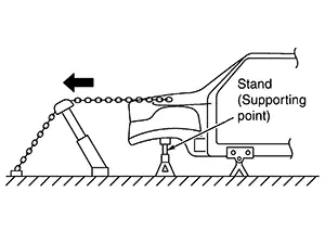
Note that if there is distance between the pulling point and the underbody clamp, as indicated by (A) in the figure, a moment of rotation is produced.
This may cause secondary damage to the clamped portion.
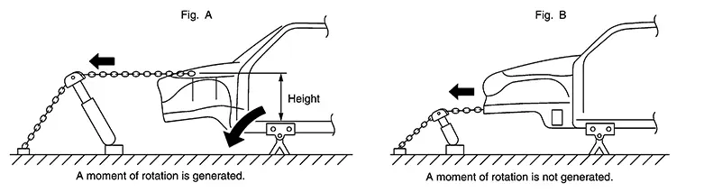
Provide a supporting point under the side member to prevent generation of this moment of rotation.
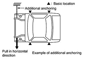
(6) ADDITIONAL ANCHORING
Pulling work must be performed with care taken not to damage the anchoring points or undamaged area of the body. If area not targeted for repair is affected by the excessive pulling force or the direction of pulling, additional anchoring points need to be provided to protect undamaged areas. Side sills are strong enough against longitudinal force, however, they are easily damaged by downward or lateral force. For this reason, additional anchoring should be provided by supporting side members with the port power, or attaching a clamp and chain.
(7) PURPOSE OF BODY ALIGNMENT
This operation is necessary to obtain correct alignment of parts to be used again. Therefore, the damage caused by propagated impact is recovered by pulling out the first input point.
Replacement of Panel
Replacement of Panel
Replacement of Panel
Panel replacement work includes replacement of the front fenders and hood which are installed by bolts, and replacement of rear fenders and the roof which are welded. This section explains panel replacement procedures after adjusting body alignment.
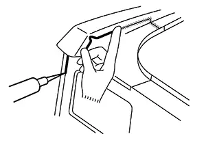
Door Hemming
Door Hemming
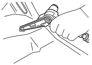
(a) Grind the edge of the door panel using 3M Cubitron II Abrasive Fibre Disc #33415 (grade 60+) or equivalent.
(b) Insert the tip of a sharp-edged tool, such as a chisel, into the clearance at door outer panel. Use a hammer to tap the tool inserted into the clearance from the side to separate the door inner panel and door outer panel.
(c) Remove the adhesive adhering to the door inner panel flange area surface.
(d) Adjust the position where the new door outer panel and door inner panel overlap. Once these are positioned correctly, fix them with clamps to prevent them from being displaced.
Apply new adhesive to both door outer panel and door inner panel.
(e) Hold the dolly on the corners of the flange at door outer panel. Tap the dolly with a hammer to bend the door outer panel flange area gradually.
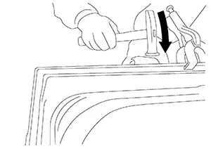
(f) Bend with hammer until the angle of the whole circumference of the door outer panel flange area becomes approximately 45°.
(g) Check that the position of the door outer panel and door inner panel is not displaced while tapping it with a hammer to bend it until the angle of whole circumference of the door outer panel flange area becomes approximately 15°.
(h) Check that the position of the door outer panel and door inner panel is not displaced while taping it with a hammer to bend it until the angle of the whole circumference of the door outer panel flange area becomes approximately 0°.
(i) Use the hemming tool [SST: KV991-10000] to adjust the shape of the whole circumference of the door outer panel flange area.
(j) Seal up the area around the hemmed end of the flange.
|
|
Door inner panel |
|
|
Door outer panel |
|
|
Adhesive |
|
|
Sealant |


Adjustment Fitting of Front Fender
Adjustment Fitting of Front Fender
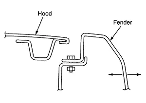
Fitting adjustment means adjustment of clearance or gradient of the hood, door, front fender, etc. with respect to its adjacent part, and adjustment of gradient at the press line.
Adjustment of front fender is described as an example.
-
Adjust the fitting at the front fender mounting position. Tighten the front fender mounting bolts loosely, and adjust the fit by moving the front fender sideways or in the up-down direction while observing the clearance with the hood and door.
-
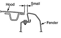
Adjust the front fender bend angle.
If a proper fit cannot be obtained by step (1) above, change the bending angle of the front fender.
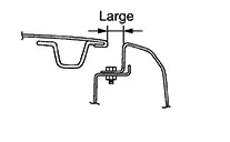
Explanation
Condition
Correction method
When the clearance between the front fender and hood is too small: Apply a flat wood plate to the upper corner of front fender, and correct by hammering. Before hammering, securely tighten the front fender mounting bolts.
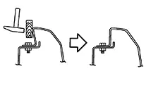
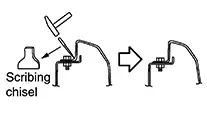
When the clearance between the front fender and hood is too large: Apply a scribing chisel to the bend at the base of the front fender. Tap with a hammer to adjust the clearance. Securely tighten the front fender mounting bolts before tapping. Apply the scribing chisel along the press line.
Adjustment Fitting of Door Assembly
Adjustment Fitting of Door Assembly
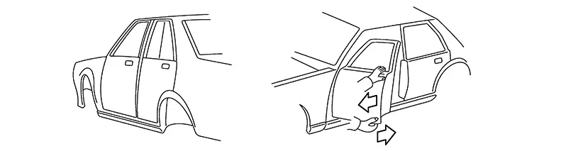
When there is excessive clearance on the upper part of door:
-
Apply a wood block between the outer sill and the lower side of door, and push the upper part of door.
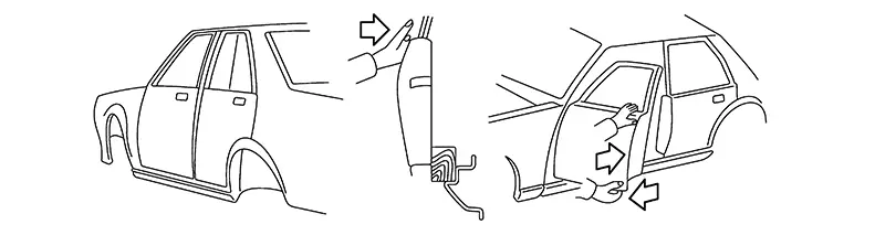
-
When there is excessive clearance on the lower part of door.
Partial Replacement of Panel (welded Panel)
Partial Replacement of Panel (welded Panel)
Partial Replacement of Panel (Welded Panel)
If damage occurs in a welded panel, it can be entirely replaced by a service panel or partial replacement can be done by cutting and replacing damaged portion with a service panel.
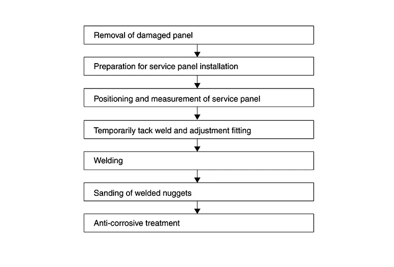
Welded Panel Replacement Procedure
Welded Panel Replacement Procedure
 Note:
Note: 
When welding and dressing the parts, cover up holes of these parts with tape to prevent debris from entering.
-
Assembly panel replacement or partial panel replacement
Assembly panel replacement means replacement of a complete panel by cutting all the welded portions.
Partial panel replacement is a method by which only the damaged portion of a panel is replaced. Partial panel replacement can be used when assembly panel replacement is too costly and time consuming, and when the damage is localized.
-
Cutting positions for partial replacement
The illustration is just example, please see each Body Repair Manual for details.
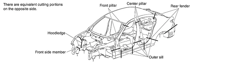
Cutting panels for partial replacement is not allowed on some portions. If panels are cut in improper portions, body strength cannot be maintained. The allowable positions vary with body structure, panel strength or shape and differ from model to model. They are indicated in the Body Repair Manual of each model. In principle, the following portions may be cut:
-
Portions without reinforcement or ducting
-
Portions where no stress concentration occurs
-
Portions with small finish area where finishing can be easily accomplished (where the connected portions can be covered by garnish or moulding)
-
Portions where work area or disassembling of parts is minimized
Rough Cutting of Panel
Rough Cutting of Panel
Most body panels are joined by spot welding. It is difficult to cut them at the welded portion.
To shorten work time, pull the damaged portion roughly, them cut near the panel joint in advance so that tools can be used properly to cut the spot welded portion. It is commonly used on panels having complicated structures.
Cutting body panel and service panels by leaving an overlap tolerance is also called rough cutting.
Use the cutting tools properly according to the portion to be cut, panel thickness, and panel structure.
Tools commonly used for this purpose and their features are described below:
(1) ROUGH CUTTING USING AN AIR SAW
(a) Major application
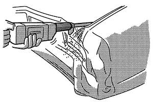
Members and pillars including side member, cross member, rear pillar, etc..
(b) Features
Clear cut line. Suitable for cutting both thin and comparatively thick sheet metal.
(2) ROUGH CUTTING USING AN AIR CHISEL
(a) Major application
Thin sheet metal including the rear fender and rear floor
(b) Features
Faster cutting speed
High noise level
Not applicable to thick sheet metal
Irregular cut line
Excessive sparking
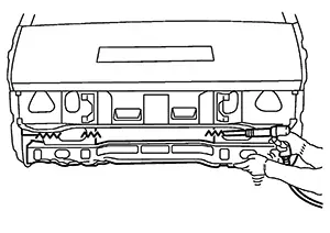
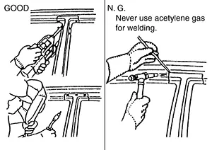
(3) ROUGH CUTTING WITH AN OXY-ACETYLENE CUTTING TORCH
(a) Major application
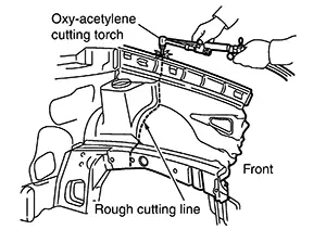
Thick sheet metal including side member, cross member, hoodledge, etc..
(b) Features
Faster cutting speed
Cutting Off Welded Portions
Cutting Off Welded Portions
A vehicle body is constructed by using three different welding methods [spot welding, MAG and brazing]. Cutting welded portion by these methods is described below.
Spot welding is generally used on two or more overlapped panels. The tool or cut off method must be changed according to whether the panel to be removed is on the top, in the middle or on the bottom.
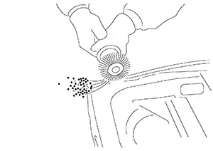
(1) CONFIRMING THE SPOT WELDED POSITION
Remove paint, undercoat, and sealer from the panel to confirm the spot welded positions.
(a) Using air sander, rotary wire brush, or file sanding belt:
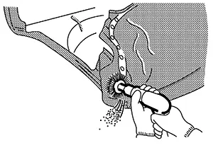
When using this method, do not grind too much of the panel. Sand or brush the panel while confirming the spot welded portion.
(b) Using a chisel:
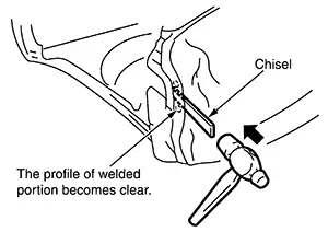
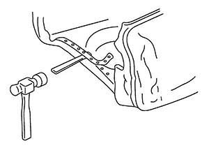
If the spot welded portion is indiscernible even after removing paint, insert the chisel blade between the panels and tap lightly with a hammer for confirmation.
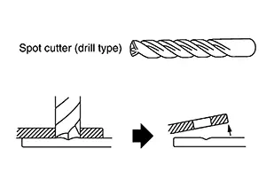
(2) CUTTING OFF SPOT WELDED PORTION
(a) Using a spot cutter:
There are two types of spot cutters (a drill type and a hole saw type). When using the spot cutter, be careful not to cut the lower panel.
 |
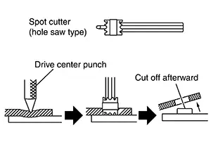 |
If it is difficult to weld from behind the lower panel, the spot cutter may be used to cut the spot welded portions without drilling the bottom panel.
The hole saw type spot cutter requires grinding of the spot weld after cutting. This requires additional work time.
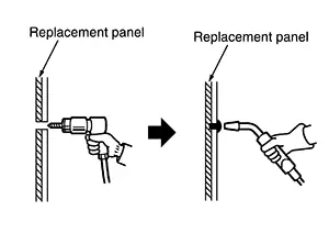
(b) Using drill:
The drill may be used to cut welds from any portion welded by plug welding, by drilling out the plug welded portion.
 |
 |
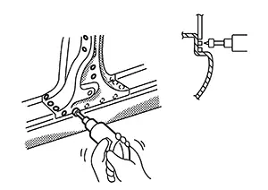
(3) CUTTING SPOT WELDED PORTIONS WITH AN AIR SANDER
If the spot cutter cannot be used, use the air sander (or belt sander) to cut off the spot welded portion. Use 3M File Belt Sander #33573 and Cubitron II File Belt Grade 60+ #33445 or equivalent.
(4) REMOVING PANEL WITH A CHISEL
After cutting the spot welded portions, separate the panel using the chisel.
By doing this, spot welded portions will separate from their mating surfaces. Thus, work can proceed while confirming the separation of spot-welded portions.
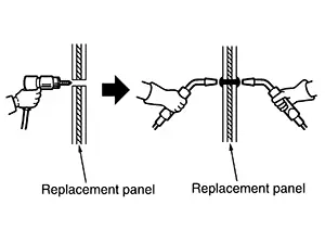
(5) CUTTING MAG WELDED PORTIONS
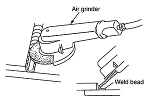
The MAG welding method is divided into two types (plug welding and seam welding). The plug weld portion can be cut off with a spot cutter or the like. To cut off the seam welded portion, grind the seam-weld bead with an air grinder to cut the welded portion. Be careful to grind from the replacement panel. Do not grind the reused panel excessively.
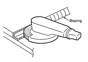
(6) CUTTING OFF BRAZED PORTION OF PANEL
Brazing is used to improve the external appearance of the joined portion (roof and fender) of the body outer panel as well as to improve sealing. Brazed portions can be generally disconnected by dissolving the braze with an oxy-acetylene torch.
If arc brazing was used, cut off the welded portion with an air sander or the like. The melting temperature of arc brazed metal is higher than that of ordinary brazing, and the panel may be damaged by this high temperature. Ordinary brazing and arc brazing may be discriminated by observing the color of the brazed metal. Ordinary brazing looks like a brass, while arc brazing has a copper color.
(a) Cutting with pneumatic saw and file belt sanding.
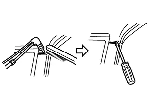
Remove the metal with a wire brush and separate the panel. While the filler metal is still hot, insert the tip of a screwdriver or the like between panels to prevent re-adhesion.
(b) Cutting with an air grinder use 3M 01991 weld grinding wheel (or equivalent)
Cut off the brazed portion with the air grinder. Do not grind excessively the panel to be reused.
Precautions for High Strength Steel (hss) and Ultra High Strength Steel (uhss)
Precautions for High Strength Steel (HSS) and Ultra High Strength Steel (UHSS)
High strength steel (HSS) means the steel from 440 MPa - 979 MPa.
Ultra high strength steel (UHSS) means the steel above 980 MPa.
(a) The repair of reinforcements (such as side members) by heating is not recommended since it may weaken the component. When heating is unavoidable, do not heat HSS parts above 550°C (1,022°F). Verify heating temperature with a thermometer. (Crayon-type and other similar type thermometer are appropriate.)
When you heat the HSS or UHSS parts above 550°C (1,022°F), it must be replaced with new parts.
(b) When straightening body panels, use caution in pulling any HSS panel. Because HSS is very strong, pulling may cause deformation in adjacent portions of the body. In this case, increase the number of measuring points, and carefully pull the HSS panel.
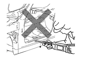
(c) When cutting HSS panels, avoid gas (torch) cutting if possible. Instead, use a saw to avoid weakening surrounding areas due to heat. If gas (torch) cutting is unavoidable, allow a minimum margin of 50 mm (1.97 in).
(d) When welding HSS panels, use spot welding whenever possible in order to minimize weakening surrounding areas due to heat.
If spot welding is impossible, use MAG welding. Do not use gas (torch) welding because it is inferior in welding strength.
(e) The spot weld on HSS panels is harder than that of an ordinary steel panel.
Therefore, when cutting spot welds on a HSS panel, use a low speed high torque drill (1,000 rpm - 1,200 rpm) to increase drill bit durability and facilitate the operation.
Prohibition for Ultra High Strength Steel (uhss)
Prohibition for Ultra High Strength Steel (UHSS)
Ultra high strength steel (UHSS) means the steel from 980 MPa or higher.
Never cut and joint the panel, plate and reinforcement made of ultra high strength steel (UHSS).
If such part is damaged, replace the part.
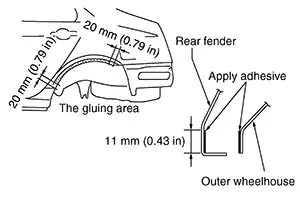
Rear Fender Hemming Process
Rear Fender Hemming Process
When the rear fender and the outer wheel housing have been joined with adhesive, the panel replacement method described below is used.
-
A wheel arch is to be installed and hemmed over left and right outer wheel house.
-
In order to hem the wheel arch, it is necessary to repair any damaged or defaced parts around outer wheel house.
CAUTION:
Ensure that the area that is to be glued around outer wheelhouse is undamaged or defaced.
Procedure of the hemming process
(a) Remove all coatings, adhesive and corrosion from the bonding area. Use abrasive that will not thin the metal.
(b) Remove all coatings, adhesive and corrosion from the bonding area. Use abrasives that will not thin metal (the replacement part).
(c) Apply new adhesive to both specified areas of outer wheelhouse and rear fender.
|
<Adhesive> |
3M™ 08115 Panel Bonding Adhesive or equivalent |
(d) Attach rear fender to the body of the car, and weld the required part except the hemming part.
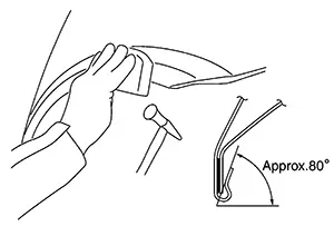
(e) Bend the welded part starting from the center of the wheel arch gradually with a hammer and a dolly. (Also hem the end of the flange.)
(f) Hemming with a hammer is conducted to an approximate angle of 80°.
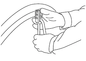
(g) Starting from the center, hem the wheel arch gradually, using slight back and forth motion with a hemming tool [SST: KV991-10000].
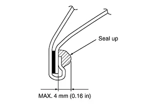
(h) Seal up the area around the hemmed end of the flange.
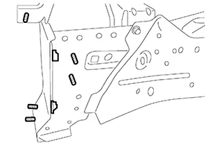
Welding Method for Stud Bolt and Nut
Welding Method for Stud Bolt and Nut
When stud bolts and weld nuts are not welded on the part acquired for repair, and are supplied as separate parts, use the following method to perform welding.
(1) FLANGE BOLT
-
Remove paint, rust, or oils on the surface of the panel.
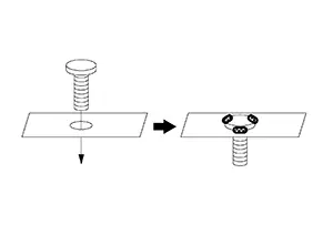
-
Insert the bolt, temporarily tighten the matching nut of the bolt, and perform centering.
-
Apply zinc weld primer to surfaces to be welded.
-
Weld 3 points evenly by MAG weld. [approximately 3 mm (0.12 in)]
-
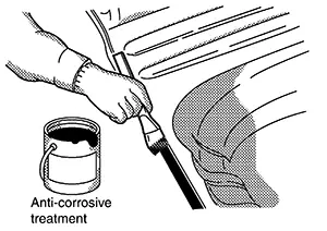
Apply an appropriate anti-corrosive treatment to the respective locations.
Note:
The same welding method is also applied when welding on a panel surface without a through hole. Welding is performed with the bolt head surface and panel contact surface contacting.
(2) WELD NUT
-
Remove paint, rust, or oils on the surface of the panel.
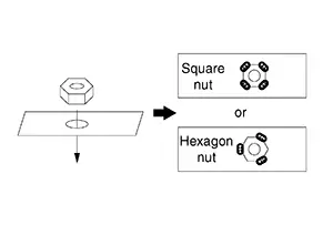
-
Put the nut on the panel center of the hole, temporarily tighten the matching bolt of the nut, and perform centering.
-
Weld 3 or 4 points evenly by MAG weld. [approximately 3 mm (0.12 in)]
-
Apply an appropriate anti-corrosive treatment to the respective locations.
Preparation for Service Panel Installation
Preparation for Service Panel Installation
After removing the damaged panel, two operations are needed. Preparation for service panel installation and finishing of the panel mounting portion of the body.
(1) FINISHING BODY
(a) Grind clean around the area where the spot-welded panel has been removed. Thoroughly remove rust and other contamination from the mating surface.
Also, remove paint from the portion to be welded.
Any brazing metal should be thoroughly removed, otherwise welding will be impaired.
(b) Irregularities on the panel mating surface prevent the panel from being welded correctly. Using a hammer and dolly, correct the shape of the mating surface.
(c) Apply weld through primer to flanges or areas where welding will be performed. Apply 3M 5917 Weld- Thru II (or equivalent) and follow product directions for MAG welding in places that cannot be painted in the subsequent painting process.
(d) If it is impossible to apply sealer after welding the service panel, sealer should be applied before welding.
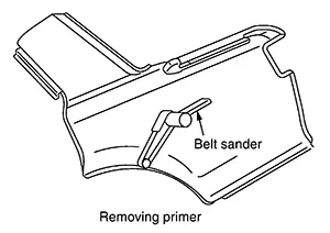
(2) PREPARATION FOR SERVICE PANEL INSTALLATION
(a) The service panel is coated with primer. Remove the primer and apply spot sealer at the portions to be welded. Do not allow the spot sealer to be forced out of the mating surface of the panel.
(b) Drill the service panel for plug welding, if necessary.
Refer to the Body Repair Manual of applicable model for the number of holes to be drilled for plug welding. The number of holes must be the same as the number of original spot welds. The drill holes must be spaced equally. Drill hole diameter must be changed according to panel thickness to maintain welding strength.
|
Panel thickness |
Plug hole dia. |
|---|---|
|
Below 1.0 mm (0.039 in) |
Below 5 mm (0.20 in) |
|
1.0 mm - 2.4 mm (0.039 in - 0.094 in) |
6.5 mm - 10 mm (0.256 in - 0.394 in) |
|
Over 2.4 mm (0.094 in) |
Over 10 mm (0.39 in) |
(3) UNDERSTANDING SERVICE PARTS
This is important in judging when the panel should be replaced, or in determining conditions for efficient operation.
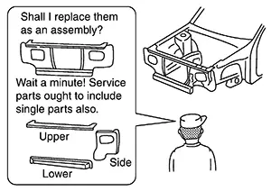
Service parts should be prepared with reference to the Parts Catalog for each model.
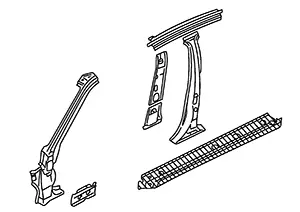
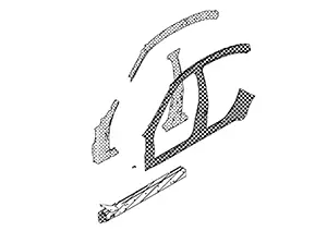
The integral type outer body side panel consists of two types of service panels. These service panels need to be cut for use depending on the location and degree of the damage.
|
Separate type outer body side panel |
Integral type outer body side panel |
|---|---|
 |
 |
Anti-Corrosive Treatment
Anti-corrosive Treatment
Anti-corrosive treatment may be performed on three different occasions (before welding, before painting, and after painting). This section explains anti-corrosive treatment for the latter two occasions.
(1) ANTI-CORROSIVE TREATMENT BEFORE PAINTING
-
Application of body sealer
Body sealer prevents water or mud from entering through the mating surface of the panel. It also prevents formation of corrosion. The sealer nozzle hole should be small. Use a finger or brush to shape the applied sealer. Refer to the Body Repair Manual for body sealer application points.
-
Application of undercoating:
Apply undercoating to the underbody and inside of wheelhouse. Do not apply it to the exhaust pipe, suspension or driving portions. Use approved products 3M Cavity Wax Plus 08852 Anti-Corrosion Spray 18oz aerosol 4 08851 Applicator Wand Kit 8", 24" and 34" tubes.
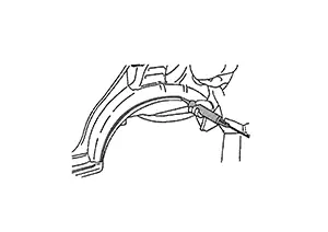
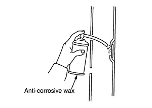
(2) ANTI-CORROSIVE WAX AFTER PAINTING
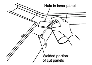
Apply anti-corrosive wax to the back of the panel where painting is difficult. Insert the nozzle of anti-corrosive wax into the holes in the inner panel. Apply until the anti-corrosive wax bleeds out from panel mating surface.
Use of Body Filler (putty) and Grinding
Use of Body Filler (putty) and Grinding
Use of Body Filler (Putty) and Grinding
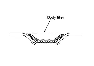
Panel irregularities may be corrected with a hammer and dolly. However, exact restoration of the original shape with these tools takes a long time. Body filler may be used to restore the original panel profile. For this purpose, the panel surface is finished slightly lower than the original surface.
Filler is applied to finish the shape and also to reduce the time needed for repair.
In body repair shops, the most commonly used materials are body filler, polyester putty, and detail putty.
This section mainly describes the body filler.
Polyester putty is described in the paint manual.
Types of Filler and Putty
Types of Filler and Putty
|
Type (Standard thickness limits) |
Characteristics |
|
|---|---|---|
|
Body Filler Putty (For repairing of large dents or scratches) [10 mm (0.39 in)] |
Surform type |
|
|
Light Type |
|
|
|
Glass Fiber or Aluminum Powder Type |
|
|
|
Intermediate Filler Putty [10 mm (0.39 in)] (For repairing of large dents or scratches) |
|
|
|
Polyester Putty (For filling pores and sand scratches in body filler) |
Spatula Type [3 mm (0.12 in)] |
|
|
Spray Type [1 mm (0.04 in)] |
|
|
|
Lacquer Putty [0.1 mm (0.004 in)] (Detail putty) |
|
|
|
Ultraviolet Curing Putty |
|
|
Putty film thickness limits should be decided with putty manufacturer because limits vary from maker to maker.
Procedure for Applying Body Filler
Procedure for Applying Body Filler
(1) REMOVAL OF PAINT
Using an air sander, remove old paint and "scuffing" the panel surface for better filler adhesion. Form a featheredge on the panel surface approximately 20 mm (0.79 in) wider than the correction area in order to eliminate traces of body filler application.
(2) CHEMICAL CONVERSION COATING
Body skin panels of NISSAN Nissan Sentra vehicles use anti-corrosive steel. These panels should be coated with a self etching primer coating before applying common body filler.
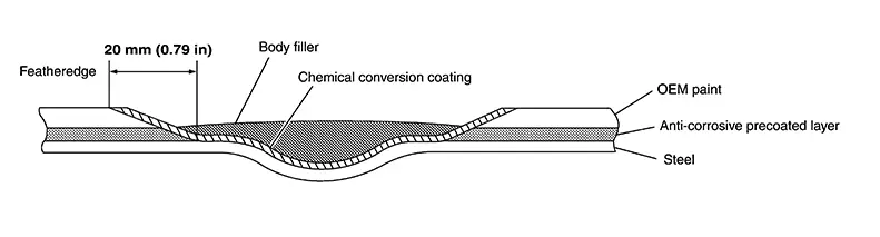
If body filler has been developed for anti-corrosive steel, chemical conversion coating will not be needed. (Please confirm this with the body filler supplier.)
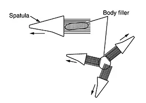
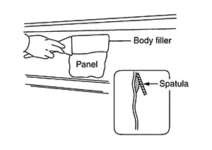
(3) SPATULA MOVEMENT
Move the spatula lengthwise when applying to an oval shaped area. If applying to a round area, move the spatula in many directions as shown in the figure.
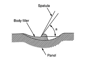
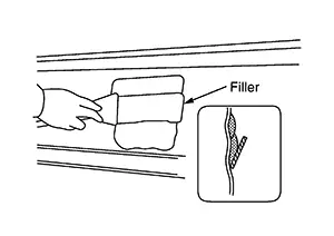
(4) APPLYING TECHNIQUE
Apply body filler in several thin layers.
(a) Hold spatula well balanced and hold slightly standing position, then squeeze putty into scratches.
|
a |
: 60°– 90° |
(b) Put a large amount of filler on the spatula.
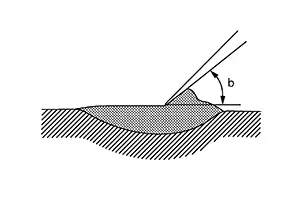
Hold spatula slightly lean, then apply several times (do not put much in once) until covered above datum level.
|
b |
: 30°– 45° |
(c) Use the spatula to smooth the applied filler.
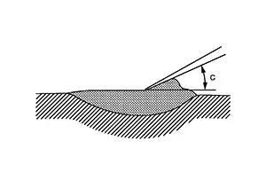
Perform finishing work for smoothening the surface. The filler surface should be slightly higher than the panel surface.
|
c |
: Less than 30° |
(5) PRECAUTION FOR APPLYING
Be careful not to place body filler over the basecoat edge. This will soften the basecoat and cause repair mapping and visible ring around the repair area. The filler edge should end on bare metal or e-coat to avoid this condition.
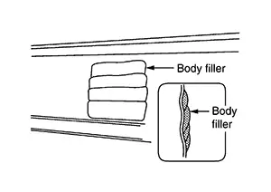
(6) APPLICATION OF BODY FILLER TO FLAT SURFACE
(a) Apply filler so that the corrected surface is flush with the surrounding panel surface.
(b) Apply another layer of filler to overlap 1/3 - 2/3 of the previous application to eliminate the step.
(c) Repeat (b) until the filler is correctly applied to the desired portion.
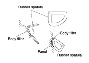
(7) APPLICATION OF BODY FILLER TO CURVED SURFACE
Use of a flexible rubber spatula is recommended for application to curved surfaces.
(8) APPLICATION OF BODY FILLER TO PRESS LINE
(A) Apply tape along the press line. Then apply filler to only one side of the press line.
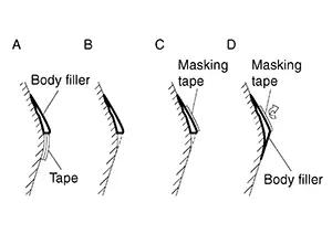
(B) Peel the tape from the half-dried filler.
(C) Apply tape along the filled and half-dried filler line.
(D) Apply filler to the other side of the press line.
Drying the Body Filler
Drying the Body Filler
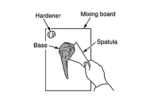
When the hardener is mixed with the base, the filler begins to harden. Heat is also generated, which accelerates hardening. For this reason, filler drying speed varies with maximum thickness allowed..
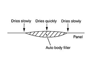
If a thick coat of filler is applied, the generated heat remains inside, hence it hardens quickly.
Where the filler is not so thick, it hardens rather slowly because heat dissipates to the outside.
Approximately 10 - 20 minutes (at 20°C or 68°F) after application, the filler becomes hard enough to permit grinding with a surform. When the ambient temperature is low, use a panel heater or adjust the drying time. To check whether the filler is dry or not, press a thin portion with finger. If it is dry, then it is suitable for grinding.
Grinding the Filled Area
Grinding the Filled Area
Grind the filler when it is half-dried. Half-dried filler means the condition where the surface, if ground lightly with a surform, will produce continuous linear chips. Grinding with the surform will be difficult after the filler hardens completely.
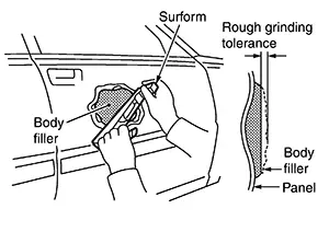
(1) ROUGH GRINDING BY SURFORM
Smooth the filler surface by grinding with the surform or the like. Grind in many different directions. Better results may be obtained if the surform is inclined 30° - 40° with respect to the direction of movement. Be careful not to damage the surrounding panel surface.
(2) ROUGH GRINGING BY AIR SANDER
Smooth the filler surface by grinding with the dual action sander or orbital sander. Grind in many different directions.
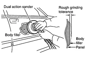
This grinding method is faster than the method using a surform. However, if the worker is not accustomed to performing this type of grinding, an uneven surface may result from excessive grinding. #80 - #120 sandpaper is used.
(3) SHAPING THE ENTIRE PANEL
Using an orbital sander or dual action sander, trim the shape of the filled panel. Leave the amount required for final finishing. #120 - #180 sandpaper is used.
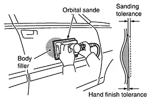
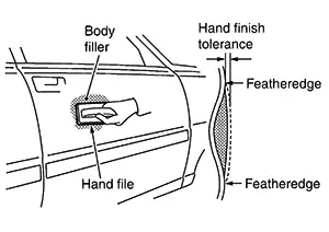
(4) FINAL FINISH BY HAND FILE
Using a hand file, orbital sander or dual action sander, smooth and form featheredge on the filler surface until it is flush with the surrounding panel. #240 - #320 sandpaper is used.
Sandpaper Grits
Sandpaper Grits
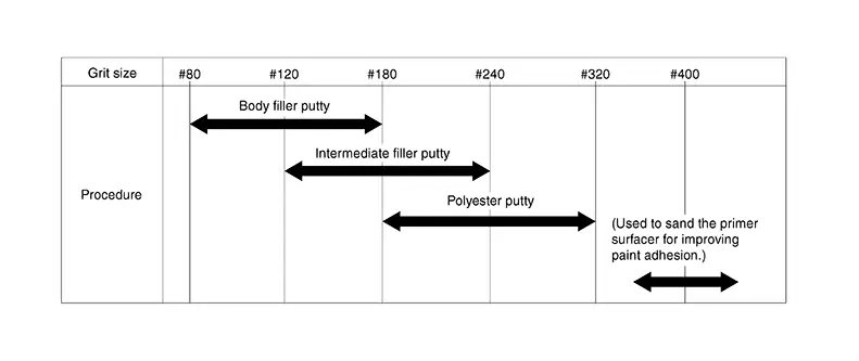
Select a sandpaper with a grit, appropriate to the putty used. Sanding marks that occur due to sanding are removed with further sanding.
SWITCHING TO A SANDPAPER OF A DIFFERENT GRIT
Sanding marks that occur during sanding are sanded with a sandpaper of the next finer grit. When doing this, do not sand using a sandpaper of a grit two grades or more finer than the previously applied sandpaper.
|
NG |
: #80 ⇒ #180 ⇒ #320 ⇒ #400 |
*: Note that, if sanding with a sandpaper of a grit two grades or more finer than the last one used, removing deep sanding marks that occur during sanding with a coarser sandpaper, as well as removing any remaining deep sanding marks may take longer.
|
OK |
: #120 ⇒ #180 ⇒ #240 ⇒ #320 ⇒ #400 |
Grinding Power of Air Sander
Grinding Power of Air Sander
The diameter (shown in the figure) of a circle traced by a part of the dual action sander and the orbital sander is called an orbit diameter. The larger the area shown with diagonal lines, the greater the grinding power is.
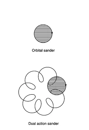
When surface accuracy is required, a sander with a smaller orbit diameter should be selected. When grinding power is required, a sander with a larger orbit diameter should be selected.
|
Work content |
Orbit diameter |
|
Sanding a body filler |
7 mm - 10 mm (0.28 in - 0.39 in) |
|
Sanding a primer surfacer |
4 mm - 5 mm (0.16 in - 0.20 in) |
|
Roughing surface before topcoating |
3 mm - 4.5 mm (0.118 in - 0.177 in) |
Repair of Rust and Corrosion
Repair of Rust and Corrosion
Repair of Rust and Corrosion
Rust on sheet metal is the result of the chemical reaction of steel to oxygen in the air, which is called oxidation. This rust, if left untreated, will increase and finally corrode and damage the sheet metal. If the Nissan Sentra vehicle is used for a long time under severe environmental conditions, rust or corrosion may form on body surfaces. When repairing rust and corrosion, it is necessary to keep rust from spreading from the repaired portion.
Removal of Rust Limited to the Skin Panel Surface
Removal of Rust Limited to the Skin Panel Surface
Grind the rusted portion with an air sander or the like.
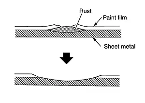
Rust may be more extensive than it appears from the outside. Therefore, it is necessary to grind the area around rusted portion. Repair the ground out portion using body filler.
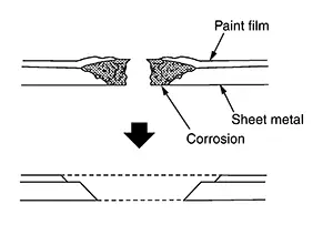
Repair of Corroded Panel
Repair of Corroded Panel
(1) FILLING WITH FIBERGLASS
(a) Grind off the corroded portion of the panel with an air sander. If corrosion is severe, cut off the affected portion with a chisel or tinman's shears. Remove the paint from the surrounding areas.
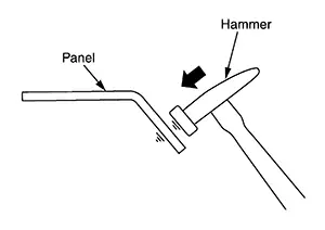
(b) Hollow the area surrounding the repair hole by tapping with a hammer and bending the panel.
(c) Cut a piece of fiberglass cloth. The cloth should be large enough to overlap the repair hole.
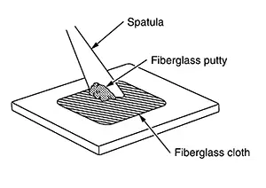
Apply fiberglass putty to the cloth using a spatula until the mesh is filled. Prepare the fiberglass putty by mixing 100 parts of base with 2 to 3 parts of hardener.
(d) Apply a thin coat of fiberglass putty to the panel where the piece of fiberglass cloth is to be attached.
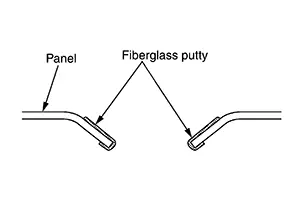
Apply putty also to the edge and back of the repair hole.
(e) Apply the piece of fiberglass cloth to the surrounding portion and the back of the repair hole.
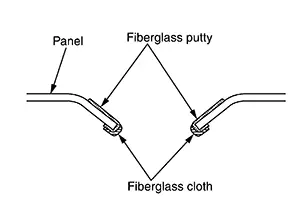
This is necessary to prevent rust.
(f) Apply the piece of fiberglass cloth prepared in step (c) above to the repair hole. Press the periphery of the cloth to the panel for better adhesion. If the repair hole is large and the cloth sags in the center, support the cloth with tape applied behind the panel.
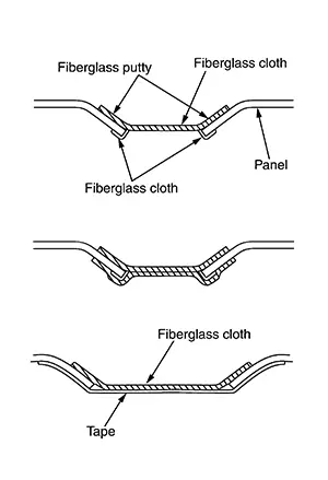
(g) Apply the fiberglass putty to the piece of fiberglass cloth. The fiberglass putty surface should be below the surrounding panel surface. If the area to be repaired is deep, use two or more piece of fiberglass cloth. In such a case, avoid thick application of fiberglass putty. Thick fiberglass putty will crack after drying.
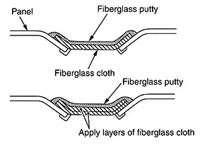
(h) Dry the fiberglass putty, and grind the surface with an air sander. Then trim the entire panel using body filler.
When force drying fiberglass putty, allow the putty to sit for approximately 20 minutes. Then heat at a temperature below 60°C (140°F). Rapid heating which causes the putty to change color must be avoided, as it will lead to cracked putty. Fiberglass putty forms blowholes easily. Body filler must be used to finish the surface of fiberglass putty.
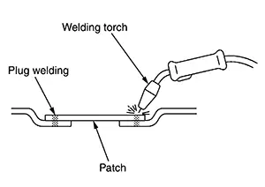
(2) PATCHING
(a) Remove the corroded portion of the panel.
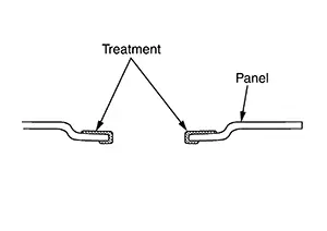
Remove paint from the panel around the repair hole.
Make a flange by bending the surrounding panel with pliers and hammer, then apply anti-corrosive treatment (Metallic solution).
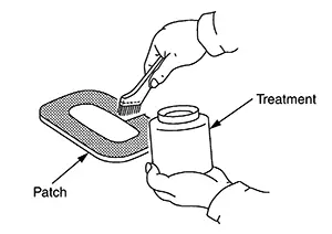
(b) Using tinman's shears, cut a patch large enough to overlap the repair hole. Apply the anti-corrosive treatment to the portion to be welded. Use of stainless steel is recommended to avoid rusting. If the repair hole is large, use a panel having the same thickness as the original panel to retain the original strength.
(c) Weld the patch to the repair hole. If stainless steel is used, use the MAG welding or spot welding method.
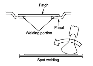 Note:
Note:
When welding the patch by MAG welding, use the plug welding method.
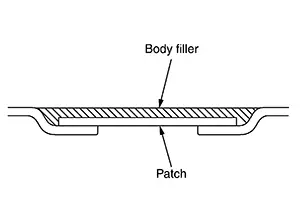
(d) Apply the body filler to the repaired portion of the panel.
(e) Apply the anti-corrosive treatment to the back of the panel. If accessible from behind, apply a sealer to the panel-to-patch mating section.
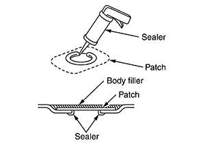
(f) If inaccessible from behind, apply an anti-corrosive wax from an inner panel opening or the like. It is also important to apply the anti-corrosive treatment to other portions in addition to the repaired portion.
Other materials:
Component Parts
Display Audio Without Bose with 8" Color Display
Component Parts Location
Component Parts Location
No.
Component
Function
...
Maintenance precautions
When performing any inspection, servicing, or maintenance work on your Nissan
Sentra, always exercise extreme care to avoid serious personal injury or accidental
damage to the vehicle. Routine maintenance plays an important role in the long-term
reliability, safety, and performance of the Niss ...
U1040 Eng Comm Circuit
Dtc Description
DTC Description
DTC DETECTION LOGIC
DTC
CONSULT screen terms
(Trouble diagnosis
content)
DTC detection
condition
...