Nissan Sentra B18 (2020-2025) Service Manual: Component Parts
Display Audio Without Bose with 8" Color Display
Component Parts Location
Component Parts Location
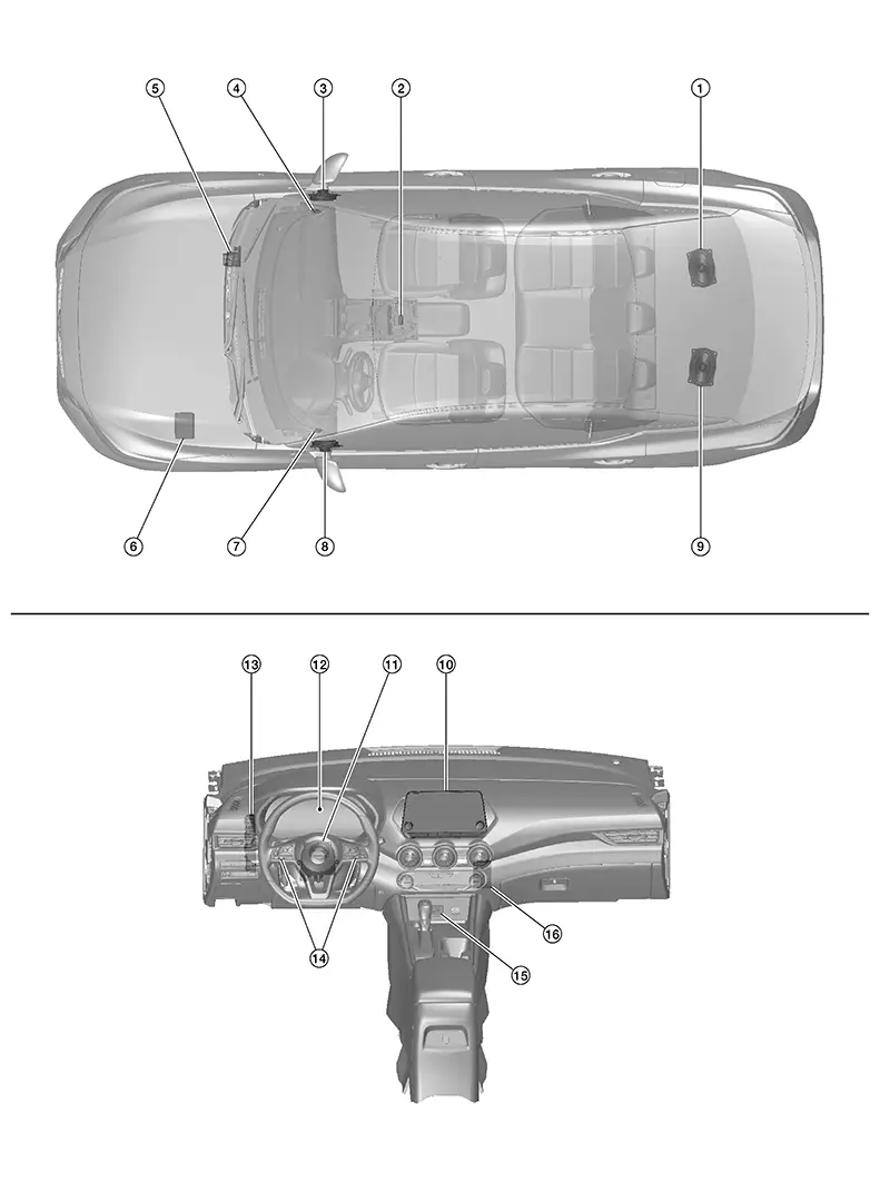
|
No. |
Component |
Function |
|---|---|---|
|
1. |
Rear speaker RH |
Refer to Speakers. |
|
2. |
Microphone |
Refer to Microphone. |
|
3. |
Front door speaker RH |
Refer to Speakers. |
|
4. |
Front tweeter RH |
|
|
5. |
ABS (Anti-lock Braking System) actuator and electric unit (control unit) |
Provides AV control unit with Nissan Sentra vehicle speed signal via CAN communication. Refer to Component Parts Location for detailed component location. |
|
6. |
IPDM E/R (Intelligent Power Distribution Module Engine Room) |
Provides AV control unit with the following signals via CAN communication:
Refer to Component Parts Location for detailed component location. |
|
7. |
Front tweeter LH |
Refer to Speakers. |
|
8. |
Front door speaker LH |
|
|
9. |
Rear speaker LH |
|
|
10. |
AV control unit |
Refer to AV control Unit. |
|
11. |
Combination switch (spiral cable) |
Provides a pass-through for the steering switch signals from the steering switches to the combination meter. |
|
12. |
Combination meter |
Refer to Component Parts Location for detailed component location. |
|
13. |
BCM (Body Control Module) |
Provides AV control unit with the following signals via CAN communication:
Refer to Component Parts Location for detailed component location. |
|
14. |
Steering switches |
Refer to Steering Switches. |
|
15. |
Front auxiliary input jacks |
Refer to Front Auxiliary Input Jacks. |
|
16. |
Front auxiliary input jacks control unit |
Refer to Front Auxiliary Input Jacks Control Unit. |
Av Control Unit
AV Control Unit
-
A 8-inch color display with multi-touch control, an AM/FM/HD electronic tuner radio with RDS, audio amplifier and camera controller are integrated into the AV control unit.
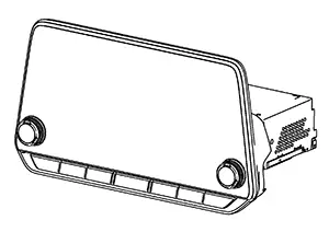
-
The 8-inch color display is a high resolution monitor that includes touch panel functions.
-
Music files stored in iPod®*/USB memory can be played using the separate USB interface.
-
Music files stored in an external audio device can be played using the separate AUX input jack.
Speakers
Speakers
FRONT TWEETER
-
2.5 cm (1 in) tweeters are installed in the front pillar finisher.
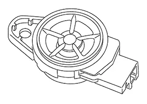
-
Sound signals are input from the AV control unit to output high range sounds.
FRONT DOOR SPEAKER
-
16.5 cm (6.5 in) speakers are installed in the bottom of the front doors.
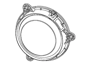
-
Sound signals are input from the AV control unit to output mid range sounds.
REAR SPEAKER
-
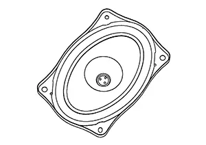
15.2 x 22.9 cm (6 x 9 in) speakers are installed in the parcel shelf.
-
Sound signals are input from the AV control unit to output low range sounds.
Front Auxiliary Input Jacks Control Unit
Front Auxiliary Input Jacks Control Unit
-
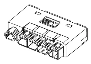
Front auxiliary input jacks control unit is installed behind the A/C switch assembly.
-
The USB interface signals from the front auxiliary input jacks are transferred to the AV control unit.
Front Auxiliary Input Jacks
Front Auxiliary Input Jacks
-
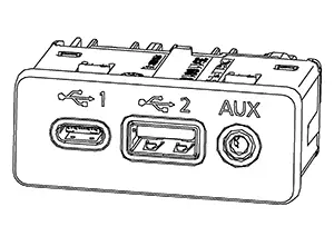
Front auxiliary input jacks are installed in the console.
-
iPod® and USB memory can be connected to the AV control unit through the USB interfaces.
-
An external audio device can be connected to the AV control unit through the AUX in jack.
Steering Switches
Steering Switches
-
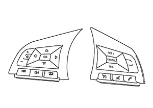
Steering switches are installed in the steering wheel.
-
Operations for audio and hands-free phone are possible.
-
Switches are connected to the combination meter.
-
Combination meter is connected to the AV control unit via AV communication.
Microphone
Microphone
-
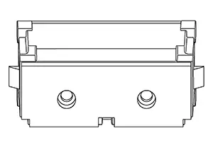
The microphone is installed in the roof in the map lamp assembly.
-
The microphone is used for operation of hands-free phone system and voice recognition function.
-
Power is supplied from the AV control unit.
Antenna and Antenna Feeder
Antenna and Antenna Feeder
SATELLITE ANTENNA
-
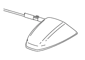
Satellite radio antenna is installed on the rear center of the roof.
-
It receives satellite radio waves and outputs them to AV control unit.
WINDOW ANTENNA
-
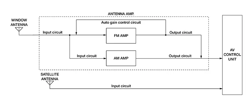
AM/FM radio antenna is installed in the rear window glass.
-
It receives radio waves and outputs them to antenna amp.
-
Antenna amp. outputs amplified radio waves to AV control unit.
-
The AM/FM radio antenna and antenna amp. obtain sufficient reception power.
ANTENNA FEEDER LAYOUT
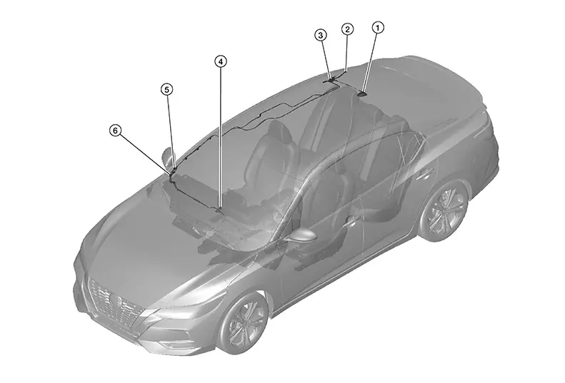
|
1. |
Satellite antenna |
2. |
R154 |
3. |
Antenna amp., R152, R153 |
|
4. |
M115, M121 |
5. |
M107, R151 |
6. |
M112, R150 |
Other materials:
Egr Cooler
Exploded View
Exploded View
1.
Vacuum delay valve
bracket
2.
EGR cooler
bracket
...
Torque Converter Clutch Solenoid Circuit
Diagnosis Procedure
Diagnosis Procedure
CHECK HARNESS CONNECTOR
Ignition switch OFF.
Check the mating condition of TCM
harness connector and CVT unit harness
connector.
Is the inspect ...
Optical Sensor Circuit
Component Function Check
Component Function
Check
CHECK OPTICAL SENSOR SIGNAL
Ignition switch ON.
Turn lighting switch AUTO.
With the optical sen ...