Nissan Sentra Service Manual: S connector circuit
Description
The starter motor magnetic switch is supplied with power when the ignition switch is turned to the START position while the selector lever is in the P (Park) or N (Neutral) position (CVT Models) or the clutch pedal is depressed (M/T Models).
Diagnosis Procedure
Regarding Wiring Diagram information, refer to STR-10, "Wiring Diagram" (with Intellignet Key system) or STR-15, "Wiring Diagram" (without Intelligent Key system).
CAUTION:
Perform diagnosis under the condition that engine cannot start by the following procedure.
- Remove fuel pump fuse.
- Crank or start the engine (where possible) until the fuel pressure is released.
1.CHECK –≤–Ç—öS–≤–Ç—ú CONNECTOR CIRCUIT
- Turn ignition switch OFF.
- Disconnect starter motor connector.
- Shift selector lever to –≤–Ç—öP–≤–Ç—ú (Park) or –≤–Ç—öN–≤–Ç—ú (Neutral) position (CVT Models) or the clutch pedal is depressed (M/T Models).
- Check voltage between starter motor harness connector F28 and ground.
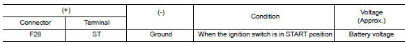
Is the inspection result normal? YES >> –≤–Ç—öS–≤–Ç—ú circuit is OK. Further inspection is necessary. Refer to STR-20, "Work Flow (With GR8-1200 NI)" or STR-24, "Work Flow (Without GR8-1200 NI)".
NO >> GO TO 2.
2.CHECK HARNESS CONTINUITY (OPEN CIRCUIT)
- Disconnect IPDM E/R connector.
- Check continuity between starter motor harness connector F28 and the IPDM E/R harness connector E44.
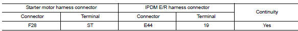
Is the inspection result normal? YES >> Further inspection is necessary. Refer to STR-20, "Work Flow (With GR8-1200 NI)" or STR-24, "Work Flow (Without GR8-1200 NI)".
NO >> Repair or replace the harness or connectors.
 B terminal circuit
Description
Terminal –≤–Ç—öB–≤–Ç—ú is constantly supplied with battery power.
Diagnosis Procedure
Regarding Wiring Diagram information, refer to STR-10, "Wiring Diagram" (with
Intellig ...
 Symptom diagnosis
Starting system
Symptom table
Symptom
Reference
No normal cranking
Refer to STR-20, "Work Flow (With GR8-1200 NI)" or
STR-24, "Work Flow (Without GR8-1200 NI ...
Other materials:
P0117, P0118 ECT Sensor
DTC Logic
DTC DETECTION LOGIC
DTC No.
CONSULT screen terms
(Trouble diagnosis content)
DTC detecting condition
Possible cause
P0117
ECT SEN/CIRC
(Engine coolant temperature
sensor 1 circuit low)
An excessively low voltage from the engine
coolant temperatu ...
Seat belts
The seat belts can be cleaned by wiping them
with a sponge dampened in a mild soap solution.
Allow the belts to dry completely in the shade
before using them. See “Seat belt maintenance”
in the “Safety – Seats, seat belts and supplemental
restraint system” section of this manual.
...
M&A branch line circuit
Diagnosis procedure
1.Check connector
Turn the ignition switch off.
Disconnect the battery cable from the negative terminal.
Check the terminals and connectors of the combination meter for damage,
bend and loose connection
(unit side and connector side).
Is the inspection result nor ...
