Nissan Sentra Service Manual: B terminal circuit
Description
Terminal ą▓ąéčÜBą▓ąéč£ is constantly supplied with battery power.
Diagnosis Procedure
Regarding Wiring Diagram information, refer to STR-10, "Wiring Diagram" (with Intelligent Key system) or STR-15, "Wiring Diagram" (without Intelligent Key system).
CAUTION:
Perform diagnosis under the condition that the engine cannot start by the following procedure.
- Remove fuel pump fuse.
- Crank or start the engine (where possible) until the fuel pressure is released.
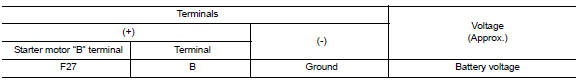
1.CHECK ą▓ąéčÜBą▓ąéč£ TERMINAL CIRCUIT
- Turn ignition switch OFF
- Check that starter motor Bą▓ąéč£ terminal connection is clean and tight.
- Check voltage between starter motor connector F27 and ground.
Is the inspection result normal? YES >> GO TO 2.
NO >> Check harness between battery and starter motor for open circuit.
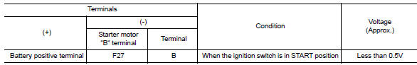
2.CHECK BATTERY CABLE CONNECTION STATUS (VOLTAGE DROP TEST)
- Shift selector lever to P (Park) or N (Neutral) position (CVT Models) or the clutch pedal is depressed (M/T Models).
- Check voltage between battery positive terminal and starter motor B terminal.
Is the inspection result normal? YES >> GO TO 3.
NO >> Check harness between the battery and starter motor for continuity.
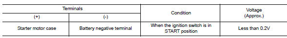
3.CHECK GROUND CIRCUIT STATUS (VOLTAGE DROP TEST)
- Shift selector lever to P (Pack) or N (Neutral) position (CVT Models) or the clutch pedal is depressed (M/T Models).
- Check voltage between starter motor case and battery negative terminal.
Is the inspection result normal? YES >> ą▓ąéčÜBą▓ąéč£ terminal circuit is OK. Further inspection is necessary. Refer to STR-20, "Work Flow (With GR8-1200 NI)" or STR-24, "Work Flow (Without GR8-1200 NI)".
NO >> Check the starter motor case to engine mounting for high resistance.

 S connector circuit
Description
The starter motor magnetic switch is supplied with power when the ignition
switch is turned to the START position
while the selector lever is in the P (Park) or N (Neutral) position (C ...
Other materials:
Warning/indicator lights and audible reminders
Anti-lock Braking System (ABS)
warning light
Brake warning light
Charge warning light
Door open warning light
Engine oil pressure warning
light
Low fuel warning light
Low tire pressure warning light
Low windshield-washer fluid
warning light
NISSAN Intelligent Key® lock
warni ...
Does not stop fully-open or fullyclosed
position
Diagnosis procedure
1. Perform initialization procedure
Perform initialization procedure.
Refer to RF-18, "ADDITIONAL SERVICE WHEN REPLACING CONTROL UNIT : Special Repair
Requirement".
Is the inspection result normal?
YES >> Inspection End.
NO >> Perform basic ins ...
FM/AM/SAT radio with compact disc (CD) player (Type A) (if so equipped)
For all operation precautions, see ŌĆ£Audio operation
precautionsŌĆØ in this section.
Audio main operation
VOL (volume) knob / PWR (power) button:
Place the ignition switch in the ACC or ON
position and press the VOL (volume) knob /PWR
(power) button while the system is off to call up
the mod ...
