Nissan Sentra Service Manual: P0456 EVAP Control system
DTC Logic
DTC DETECTION LOGIC
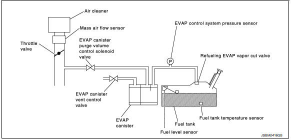
This diagnosis detects leaks in the EVAP line between fuel tank and EVAP canister purge volume control solenoid valve, using the negative pressure caused by decrease of fuel temperature in the fuel tank after turning ignition switch OFF.
If ECM judges there are no leaks, the diagnosis will be OK.
| DTC No. | CONSULT screen terms (Trouble diagnosis content) | DTC detecting condition | Possible cause |
| P0456 | EVAP VERY SML LEAK [Evaporative emission system leak detected (very small leak)] |
|
|
CAUTION:
- Use only a genuine NISSAN fuel filler cap as a replacement. If an incorrect fuel filler cap is used, the MIL may illuminate.
- If the fuel filler cap is not tightened properly, the MIL may illuminate.
- Use only a genuine NISSAN rubber tube as a replacement.
DTC CONFIRMATION PROCEDURE
1.PRECONDITIONING
If DTC Confirmation Procedure has been previously conducted, always perform the following before conducting the next test.
- Turn ignition switch OFF and wait at least 10 seconds.
- Turn ignition switch ON.
- Turn ignition switch OFF and wait at least 10 seconds.
Do you have CONSULT? YES >> GO TO 2.
NO >> GO TO 4.
2.PERFORM DTC CONFIRMATION PROCEDURE-1
 WITH CONSULT
- Turn ignition switch ON and select ĐČĐŃEVAP DIAG READYĐČĐŃ in ĐČĐŃDATA MONITORĐČĐŃ mode of ĐČĐŃENGINEĐČĐŃ using CONSULT.
- Start engine and wait at idle until ĐČĐŃOFFĐČĐŃ of ĐČĐŃEVAP DIAG READYĐČĐŃ changes to ĐČĐŃONĐČĐŃ.
NOTE:
It will take at most 2 hours until ĐČĐŃOFFĐČĐŃ of ĐČĐŃEVAP DIAG READYĐČĐŃ changes to ĐČĐŃONĐČĐŃ.
- Turn ignition switch OFF and wait at least 90 minutes.
NOTE:
Never turn ignition switch ON during 90 minutes.
- Turn ignition switch ON and select ĐČĐŃEVAP LEAK DIAGĐČĐŃ in ĐČĐŃDATA MONITORĐČĐŃ mode of ĐČĐŃENGINEĐČĐŃ using CONSULT
- Check that ĐČĐŃEVAP LEAK DIAGĐČĐŃ indication.
Which is displayed on CONSULT? CMPLT>> GO TO 3.
YET >> Perform DTC CONFIRMATION PROCEDURE again. GO TO 1.
3.PERFORM DTC CONFIRMATION PROCEDURE-2
Check 1st trip DTC.
Is 1st trip DTC detected? YES >> Proceed toEC-321, "Diagnosis Procedure".
NO >> INSPECTION END.
4.PERFORM DTC CONFIRMATION PROCEDURE
 WITH GST
- Start engine and wait engine idle for at least 2 hours.
- Turn ignition switch OFF and wait at least 90 minutes.
NOTE:
Never turn ignition switch ON during 90 minutes.
- Turn ignition switch ON.
- Check 1st trip DTC.
Is 1st trip DTC detected? YES >> Proceed to EC-321, "Diagnosis Procedure".
NO >> INSPECTION END.
Diagnosis Procedure
1.CHECK FUEL FILLER CAP DESIGN
- Turn ignition switch OFF.
- Check for genuine NISSAN fuel filler cap design.
Is the inspection result normal? YES >> GO TO 2.
NO >> Replace with genuine NISSAN fuel filler cap.
2.CHECK FUEL FILLER CAP INSTALLATION
Check that the cap is tightened properly by rotating the cap clockwise.
Is the inspection result normal? YES >> GO TO 3.
NO >> Open fuel filler cap, then clean cap and fuel filler neck threads using air blower. Then retighten until reteaching sound is heard.
3.CHECK FUEL FILLER CAP FUNCTION
Check for air releasing sound while opening the fuel filler cap.
Is the inspection result normal? YES >> GO TO 5.
NO >> GO TO 4.
4.CHECK FUEL TANK VACUUM RELIEF VALVE
Refer to EC-325, "Component Inspection".
Is the inspection result normal? YES >> GO TO 5.
NO >> Replace fuel filler cap with a genuine one.
5.CHECK FOR EVAP LEAK
Refer to EC-482, "Inspection".
Is there any leak in EVAP line? YES >> Repair or replace.
NO >> GO TO 6.
6.CHECK EVAP CANISTER VENT CONTROL VALVE
Check the following.
- EVAP canister vent control valve is installed properly.
Refer to FL-14, "Exploded View".
- EVAP canister vent control valve.
Refer to FL-15, "Removal and Installation".
Is the inspection result normal? YES >> GO TO 7.
NO >> Repair or replace EVAP canister vent control valve and O-ring. Refer to FL-15, "Removal and Installation".
7.CHECK IF EVAP CANISTER SATURATED WITH WATER
- Remove EVAP canister with EVAP canister vent control valve and EVAP control system pressure sensor attached.
- Check if water will drain from the EVAP canister.
Does water drain from EVAP canister? YES >> GO TO 8.
NO-1 >> With CONSULT: GO TO 10.
NO-2 >> Without CONSULT: GO TO 11.
8.CHECK EVAP CANISTER
Weigh the EVAP canister assembly with the EVAP canister vent control valve and EVAP control system pressure sensor attached. Refer to FL-15, "Removal and Installation".
The weight should be less than 2.1 kg (4.6 lb).
Is the inspection result normal? YES-1 >> With CONSULT: GO TO 10.
YES-2 >> Without CONSULT: GO TO 11.
NO >> GO TO 9.
9.DETECT MALFUNCTIONING PART
Check the following.
- EVAP canister for damage
- EVAP hose between EVAP canister and vehicle frame for clogging or poor connection
>> Repair hose or replace EVAP canister. Refer to FL-15, "Removal and Installation".
10.CHECK EVAP CANISTER PURGE VOLUME CONTROL SOLENOID VALVE OPERATION
 With CONSULT
- Disconnect vacuum hose to EVAP canister purge volume control solenoid valve at EVAP service port.
- Start engine and let it idle.
- Select ĐČĐŃPURG VOL CONT/VĐČĐŃ in ĐČĐŃACTIVE TESTĐČĐŃ mode of ĐČĐŃENGINEĐČĐŃ using CONSULT.
- Touch ĐČĐŃQuĐČĐŃ on CONSULT screen to increase ĐČĐŃPURG VOL CONT/VĐČĐŃ opening to 100%.
- Check vacuum hose for vacuum.
Vacuum should exist.
Is the inspection result normal? YES >> GO TO 13.
NO >> GO TO 12.
11.CHECK EVAP CANISTER PURGE VOLUME CONTROL SOLENOID VALVE OPERATION
 Without CONSULT
- Start engine and warm it up to normal operating temperature.
- Stop engine.
- Disconnect vacuum hose to EVAP canister purge volume control solenoid valve at EVAP service port.
- Start engine and let it idle for at least 80 seconds.
- Check vacuum hose for vacuum when revving engine up to 2,000 rpm.
Vacuum should exist.
Is the inspection result normal? YES >> GO TO 13.
NO >> GO TO 12.
12.CHECK VACUUM HOSE
Check vacuum hoses for clogging or disconnection.
Is the inspection result normal?
YES >> GO TO 13.
NO >> Repair or reconnect the hose.
13.CHECK EVAP CANISTER PURGE VOLUME CONTROL SOLENOID VALVE
Check the EVAP canister purge volume control solenoid valve. Refer to EC-296, "Component Inspection".
Is the inspection result normal? YES >> GO TO 14.
NO >> Replace EVAP canister purge volume control solenoid valve. Refer to EM-27, "Exploded View".
14.CHECK FUEL TANK TEMPERATURE SENSOR
Check the fuel tank temperature sensor. Refer to EC-257, "Component Inspection".
Is the inspection result normal? YES >> GO TO 15.
NO >> Replace fuel level sensor unit. Refer to FL-6, "Removal and Installation".
15.CHECK EVAP CONTROL SYSTEM PRESSURE SENSOR
Check the EVAP control system pressure sensor. Refer to FL-15, "Removal and Installation".
Is the inspection result normal? YES >> GO TO 16.
NO >> Replace EVAP control system pressure sensor. Refer to FL-15, "Removal and Installation".
16.CHECK EVAP PURGE LINE
Check EVAP purge line (pipe, rubber tube, fuel tank and EVAP canister) for cracks or improper connection.
Refer to EC-49, "EVAPORATIVE EMISSION SYSTEM : System Description".
Is the inspection result normal? YES >> GO TO 17.
NO >> Repair or reconnect the hose.
17.CLEAN EVAP PURGE LINE
Clean EVAP purge line (pipe and rubber tube) using air blower.
>> GO TO 18.
18.CHECK EVAP/ORVR LINE
Check EVAP/ORVR line between EVAP canister and fuel tank for clogging, kink, looseness and improper connection.
For location, refer to EC-49, "EVAPORATIVE EMISSION SYSTEM : System Description".
Is the inspection result normal? YES >> GO TO 19.
NO >> Repair or replace hoses and tubes.
19.CHECK RECIRCULATION LINE
Check recirculation line between fuel filler tube and fuel tank for clogging, kink, cracks, looseness and improper connection.
Is the inspection result normal? YES >> GO TO 20.
NO >> Repair or replace hose, tube or fuel filler tube. Refer to FL-10, "Exploded View".
20.CHECK REFUELING EVAP VAPOR CUT VALVE
Check the refueling EVAP vapor cut valve. Refer to FL-13, "Inspection".
Is the inspection result normal? YES >> GO TO 21.
NO >> Replace refueling EVAP vapor cut valve with fuel tank. Refer to FL-10, "Removal and Installation".
21.CHECK FUEL LEVEL SENSOR
Check the fuel level sensor. Refer to MWI-59, "Component Inspection".
Is the inspection result normal? YES >> Check intermittent incident. Refer to GI-39, "Intermittent Incident".
NO >> Replace fuel level sensor unit. Refer to FL-6, "Removal and Installation".
Component Inspection
1.CHECK FUEL FILLER CAP
- Turn ignition switch OFF.
- Remove fuel filler cap.
- Wipe clean valve housing.
- Install fuel filler cap adapter (commercial service tool) to fuel filler cap.
- Check valve opening pressure and vacuum.
Pressure: 15.3 - 20.0 kPa (0.156 - 0.204 kg/cm2, 2.22 - 2.90 psi)
Vacuum: −6.0 to −3.3 kPa (−0.061 to −0.034 kg/cm2, −0.87 to −0.48 psi)
Is the inspection result normal? YES >> INSPECTION END
NO >> GO TO 2.
2.REPLACE FUEL FILLER CAP
Replace fuel filler cap.
CAUTION:
Use only a genuine fuel filler cap as a replacement. If an incorrect fuel filler cap is used, the MIL may illuminate.
>> INSPECTION END
 P0453 EVAP Control system pressure sensor
DTC Logic
DTC DETECTION LOGIC
DTC No.
CONSULT screen terms
(Trouble diagnosis content)
DTC detecting condition
Possible cause
P0453
EVAP SYS PRES SEN
(Evaporative e ...
 P0460 Fuel level sensor
DTC Logic
DTC DETECTION LOGIC
NOTE:
If DTC P0460 is displayed with DTC UXXXX, first perform the trouble
diagnosis for DTC UXXXX.
If DTC P0460 is displayed with DTC P0607, first perform the ...
Other materials:
NISSAN vehicle immobilizer system (if so equipped)
The NISSAN Vehicle Immobilizer System will not
allow the engine to start without the use of a
registered key.
If the engine fails to start using a registered key
(for example, when interference is caused by
another registered key, an automated toll road
device or automatic payment device on ...
Diagnosis system [abs actuator and electric unit (control
unit)]
CONSULT Function (ABS)
FUNCTION
CONSULT can display each diagnostic item using the following
direct diagnostic modes.
Direct Diagnostic Mode
Description
ECU identification
The ABS actuator and electric unit (control unit) part number is
displayed.
Self Diagnos ...
BluetoothÂź streaming audio with Navigation System (if so equipped)
If you have a compatible BluetoothÂź audio device
that is capable of playing audio files, the
device can be connected to the vehicleâs audio
system so that the audio files on the device play
through the vehicleâs speakers.
Connecting BluetoothÂź audio
To connect your BluetoothÂź audio ...
