Nissan Sentra B18 (2020-2025) Service Manual: Road Wheels & Tires :: Periodic Maintenance
Wheel. Inspection. Inspection
Inspection
Check tires for wear and improper inflation.
Check wheels for deformation, cracks and other damage. If deformed, remove wheel and check wheel runout.
Remove tire
from wheel and mount wheel on a balancer machine. 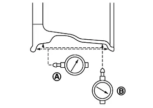
CAUTION:
DO NOT use center hole cone-type clamping machines to hold the wheel during tire removal/installation or balancing or damage to the wheel paint, cladding or chrome may result. Use only rim-type or universal lug-type clamping machines to hold the wheel during servicing.
Set dial indicator as shown. Check runout. If the lateral runout (A) or radial runout (B) exceeds the limit, replace wheel.|
Lateral runout (A) |
: Refer to Wheel. |
|
Radial runout (B) |
: Refer to Wheel. |
Wheel and Tire. Adjustment
Adjustment
BALANCING WHEELS (ADHESIVE WEIGHT TYPE)
Preparation Before Adjustment
Remove inner and outer balance weights from the wheel. Using releasing agent, remove double-faced adhesive tape from the wheel.
CAUTION:
-
Be careful not to scratch the wheel and tire during removal.
-
After removing double-faced adhesive tape, wipe clean all traces of releasing agent from the wheel and tire.
Wheel Balance Adjustment
CAUTION:
-
DO NOT use center hole cone-type clamping machines to hold the wheel during tire removal/installation or balancing or damage to the wheel paint, cladding or chrome may result. Use only rim-type or universal lug-type clamping machines to hold the wheel during servicing.
-
If a balancer machine has an adhesive weight mode setting, select the adhesive weight mode setting and skip Step 2 below. If a balancer machine only has the clip-on (rim flange) weight mode setting, follow Step 2 to calculate the correct size adhesive weight.
-
Set wheel and tire on balancer machine using the center hole as a guide. Start the balancer machine.
-
For balancer machines that only have a clip-on (rim flange) weight mode setting, follow this step to calculate the correct size adhesive weight to use. When inner and outer imbalance values are shown on the balancer machine indicator, multiply outer imbalance value by 5/3 (1.67) to determine balance weight that should be used. Select the outer balance weight with a value closest to the calculated value above and install in to the designated outer position of or at the designated angle in relation to the wheel and tire.
-
Indicated imbalance value × 5/3 (1.67) = balance weight to be installed
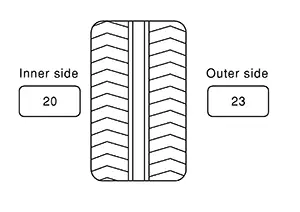
Calculation example:
23 g (0.81 oz) × 5/3 (1.67) = 38.33 g (1.35 oz) ⇒ 40 g (1.41 oz) balance weight (closer to calculated balance weight value)
Note:
Note that balance weight value must be closer to the calculated balance weight value.
Example:
37.4 ⇒ 35 g (1.23 oz)
37.5 ⇒ 40 g (1.41 oz)
-
Install balance weight in the position shown.
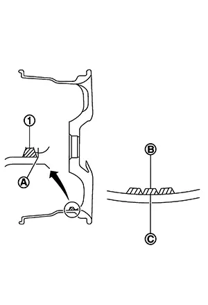
CAUTION:
-
Do not install the inner balance weight before installing the outer balance weight.
-
Before installing the balance weight, be sure to clean the mating surface of the wheel and tire.
-
When installing balance weight (1) to wheel and tire, set it into the grooved area (A) on the inner wall of the wheel and tire as shown so that the balance weight center (B) is aligned with the balancer machine indication position (angle) (C).
CAUTION:
-
Always use Genuine NISSAN adhesive balance weights.
-
Balance weights are non-reusable; always replace with new ones.
-
Do not install more than three sheets of balance weights.
-
-
-
If calculated balance weight value exceeds 50 g (1.76 oz), install two balance weight sheets in line with each other as shown.
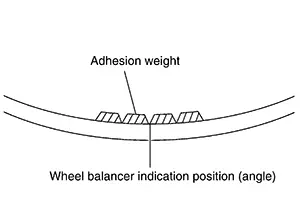
CAUTION:
Do not install one balance weight sheet on top of another.
-
-
Start balancer machine again.
-
Install balance weight on inner side of wheel and tire in the balancer machine indication position (angle).
CAUTION:
Do not install more than two balance weights.
-
Start balancer machine. Make sure that inner and outer residual imbalance values are 5 g (0.17 oz) each or below.
-
If either residual imbalance value exceeds 5 g (0.17 oz), repeat installation procedures.
|
Wheel balance |
Dynamic (At flange) |
Static (At flange) |
|---|---|---|
|
Allowable imbalance |
Refer to Wheel. |
|
BALANCING WHEELS (STEEL WHEEL)
Preparation Before Adjustment
Remove balance weight from the wheel.
Wheel Balance Adjustment
-
The details of the adjustment procedure are different for each model of balancer machine. Therefore, refer to each instruction manual.
-
If a balancer machine has an adhesive weight mode settings and a drive-in (clip-on rim flange) weight mode setting, select a drive-in weight mode suitable for steel wheels.
-
Set wheel and tire on balancer machine. Start balancer machine.
-
Install balance weight to wheel according to the imbalance and position (angle) displayed on balancer machine.
CAUTION:
-
Never install three or more balance weights on one side.
-
Always use Genuine NISSAN balance weights.
-
Balance weights are non-reusable; always replace with new ones.
-
Always use a plastic hammer when attaching the weight.
-
-
Start balancer machine. Check that the inner and outer residual imbalance value is within the allowable imbalance value.
-
If either residual imbalance value exceeds the allowable imbalance value, repeat installation procedures.
|
Wheel balance |
Dynamic (At flange) |
Static (At flange) |
|---|---|---|
|
Allowable imbalance |
Refer to Wheel. |
|
Rotation
Rotation
-
Follow the maintenance schedule for tire rotation service intervals. Refer to Explanation of General Maintenance.
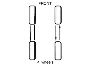
-
Rotate the wheels and tires front to back in the pattern as shown.
-
When installing the wheel, tighten wheel nuts to the specified torque.
Warning:
-
Do not include the spare tire when rotating tires.
-
After rotating tires, check and adjust the tire pressure.
CAUTION:
-
When installing wheel nuts, tighten them diagonally by dividing the work two to three times in order to prevent the wheels from developing any distortion.
-
Be careful not to tighten the wheel nuts to a torque exceeding specification to prevent strain on the disc brake rotor or brake drum.
-
Use Genuine NISSAN wheel nuts.
Wheel nut tightening torque
: Refer to Exploded View.
-
Other materials:
Fuel Pump
Component Inspection
Component Inspection
CHECK FUEL PUMP
Turn ignition switch OFF.
Disconnect “fuel level sensor
unit and fuel pump� harness connector.
Check the resistance between
...
Action Test
Ldw
Work Procedure
Work Procedure
Perform action test to verify the customer's
concern.
Perform action test and check the system operation after
system diagnosis.
Warning:
Be careful of traffic conditions and safety around the
...
P0447 Evap Canister Vent Control Valve
Dtc Description
DTC Description
DTC DETECTION LOGIC
DTC
CONSULT screen terms
(Trouble diagnosis
content)
DTC detection
condition
...