Nissan Sentra B18 (2020-2025) Service Manual: Removal and Installation
Av Control Unit
Exploded View
Exploded View
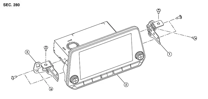
|
1. |
AV control unit bracket (LH) |
2. |
AV control unit |
3. |
AV control unit bracket (RH) |
Removal and Installation
Removal and Installation
REMOVAL
CAUTION:
When replacing AV control unit, perform "ADDITIONAL SERVICE WHEN REPLACING AV CONTROL UNIT. Refer to Description.
Disconnect the negative battery terminal. Refer to Battery Disconnect.
Remove cluster lid C. Refer to Removal and Installation
Remove the AV control unit screws, then pull out the AV control unit.
Disconnect the harness connectors from the AV control unit and remove.
If necessary, remove the AV control unit bracket (LH/RH) screws and the AV control unit brackets (LH/RH).
INSTALLATION
Installation is in the reverse order of removal.
CAUTION:
When replacing AV control unit, perform "ADDITIONAL SERVICE WHEN REPLACING AV CONTROL UNIT". Refer to Description.
Around View Monitor Control Unit
Removal and Installation
Removal and Installation
REMOVAL
CAUTION:
When replacing around view monitor control unit, perform "ADDITIONAL SERVICE WHEN REPLACING AROUND VIEW MONITOR CONTROL UNIT". Refer to Description.
Remove passenger side seat. Refer to Removal and Installation — Seat Assembly.
Partially remove passenger side floor trim. Refer to Exploded View.
Remove
screws (A) from around view monitor control unit (1). 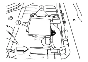
|
|
: Front |

Disconnect the harness connector from the around view monitor control unit and remove.
INSTALLATION
Installation is in the reverse order of removal.
CAUTION:
-
Replace the around view monitor control unit if it has been dropped or sustained an impact.
-
When replacing around view monitor control unit, perform "ADDITIONAL SERVICE WHEN REPLACING AROUND VIEW MONITOR CONTROL UNIT". Refer to Description.

Perform camera image calibration. Refer to Description.
Front Camera
Removal and Installation
Removal and Installation
REMOVAL
Remove clips (A) and core support
cover (1). 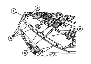
Remove screws (A) from front bumper
fascia (2). 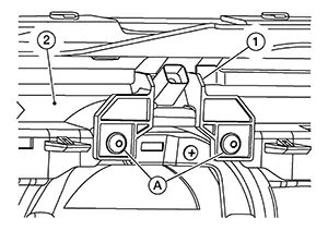
Disconnect harness connector from front camera (1) and remove.
INSTALLATION
Installation is in the reverse order of removal.
Note:
Perform "CALIBRATING CAMERA IMAGE (INTELLIGENT AROUND VIEW MONITOR)". Refer to Description.
Door Mirror Camera
Removal and Installation
Removal and Installation
REMOVAL
Remove door mirror cover. Refer to Removal and Installation.
Using a
suitable tool, release pawls from back side of door mirror
housing. 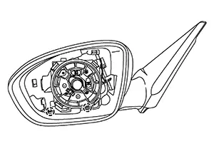
|
|
: Pawl |

Remove
screws (A) from door mirror housing (1). 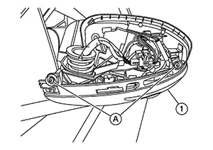
Using a
suitable tool, release pawls from front side of door mirror housing
(1) and split door mirror housing halves. 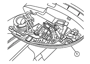
|
|
: Pawl |
Remove
screw (A) and door mirror camera (1). 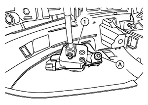
INSTALLATION
Installation is in the reverse order of removal.
Note:
Perform camera image calibration. Refer to Description.
Rear View Camera
Removal and Installation
Removal and Installation
Removal
Remove trunk lid finisher. Refer to Removal and Installation.
Remove
trunk lid damper bolts (A) and trunk lid damper (1). 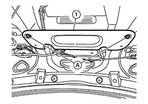
Disconnect the rear view camera harness connector.
Using a
suitable tool, release pawl and remove rear view camera (1). 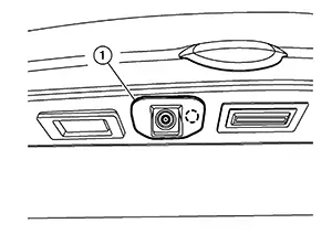
Installation
Installation is in the reverse order of removal.
Note:
Perform camera image calibration. Refer to Description.
Other materials:
Types of tires
WARNING
When changing or replacing tires on your Nissan Sentra, always ensure
that all four tires are of the same type (Summer, All Season, or Snow) and the
same construction. A NISSAN dealer can assist you in selecting the correct tire
type, size, speed rating, and availability suitabl ...
C1608-54 Control Unit
Dtc Description
DTC Description
DTC DETECTION LOGIC
DTC No.
CONSULT screen terms
(Trouble diagnosis content)
DTC detection condition
...
B20ce-15 Hl (hi) Lh Pwr Sply Circ
Dtc Description
DTC Description
DTC DETECTION LOGIC
DTC No.
CONSULT screen items
(Trouble diagnosis content)
DTC detection condition
...