Nissan Sentra Service Manual: Removal and installation
Starter motor
Exploded View
- “S” terminal harness
- “B” terminal harness
- Starter motor
- Cylinder block
Removal and Installation
NOTE:
When removing components such as hoses, tubes/lines, etc., cap or plug openings to prevent fluid from spilling.
REMOVAL
- Disconnect the battery negative terminal. Refer to PG-50, "Removal and Installation (Battery)".
- Remove fan shroud and motor assembly. Refer to CO-17, "Component".
- Remove reservoir hose upper from radiator to water outlet. Refer to CO-15, "Exploded View".
- Remove “B” terminal nut and “B” terminal harness.
- Remove “S” terminal nut and “S” terminal harness.
- Disconnect harness connector from oil temperature sensor. Refer to EM-94, "Exploded View".
- Disconnect harness connector (1) from crankshaft position sensor.
- Remove harness clip (A) from oil pan (upper), and then remove harness (2) and set aside.
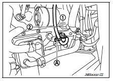
- Remove upper starter motor bolt.
- Remove lower starter motor bolt and remove starter motor.
- Installation is in the reverse order of removal.
- Refill engine coolant. Refer to CO-12, "Changing Engine Coolant".
CAUTION:
- Be careful to tighten "B" terminal nut to the specified torque.
 Symptom diagnosis
Starting system
Symptom table
Symptom
Reference
No normal cranking
Refer to STR-20, "Work Flow (With GR8-1200 NI)" or
STR-24, "Work Flow (Without GR8-1200 NI ...
 Service data and specifications (SDS)
Starter Motor
*: Always check with the Parts Department for the latest parts information. ...
Other materials:
Child safety
WARNINGDo not allow children to play with the
seat
belts. Most seating positions are
equipped with Automatic Locking Retractor
(ALR) mode seat belts. If the seat belt
becomes wrapped around a child’s neck
with the ALR mode activated, the child can
be seriously injured ...
Ecu diagnosis information
Audio unit
Reference value
TERMINAL LAYOUT
PHYSICAL VALUES
1: without BluetoothВ®
2: with BluetoothВ®
BluetoothВ® control unit
Reference value
TERMINAL LAYOUT
PHYSICAL VALUES
...
Illumination control switch
Removal and installation
Removal
Remove instrument finisher d. Refer to ip-14, "exploded view".
Remove the illumination control switch (1) from the switch carrier
(2) using suitable tool (a).
: Pawl
Installation
Installation is in the reverse order of removal. ...
