Nissan Sentra B18 (2020-2025) Service Manual: Removal and Installation
Front Combination Lamp
Exploded View
Exploded View
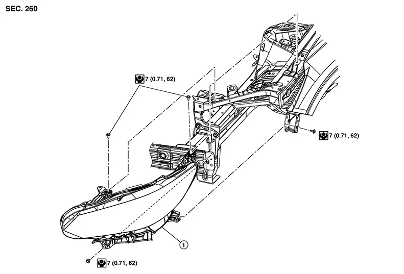
|
1. |
Front combination lamp |
Removal and Installation
Removal and Installation
REMOVAL
Remove the front bumper fascia. Refer to Removal and Installation.
Remove the front combination lamp bolts.
Pull the front combination lamp forward.
Disconnect the harness connectors from the front combination lamp.
INSTALLATION
Installation is in the reverse order of removal.
After installation, perform headlamp aiming adjustment. Refer to Aiming Adjustment.
Bulb Replacement
Bulb Replacement
Warning:
Do not touch bulb by hand while it is lit or right after being turned off. Burning may result.
CAUTION:
-
Do not touch glass surface of the bulb with bare hands or allow oil or grease to get on it to prevent damage to bulb.
-
Do not leave the bulb out of the lamp reflector for a long time because dust, moisture, smoke, etc. may affect the performance of the lamp.
HEADLAMP HIGH BEAM/ DAYTIME RUNNING LAMP BULB
Removal
Remove the core support cover. Refer to Exploded View.
Rotate the plastic cover counterclockwise and remove.
Rotate the headlamp high beam/daytime running lamp bulb counterclockwise and remove.
Disconnect the harness connector from the headlamp high beam/daytime running lamp bulb.
Installation
Installation is in the reverse order of removal.
CAUTION:
After installing, be sure to install the cover securely to ensure watertightness.
HEADLAMP LOW BEAM LAMP BULB
Removal
Remove the core support cover. Refer to Exploded View.
Rotate the plastic cover counterclockwise and remove.
Rotate the headlamp low beam lamp bulb counterclockwise and remove.
Disconnect the harness connector from the headlamp low beam lamp bulb.
Installation
Installation is in the reverse order of removal.
CAUTION:
After installing, be sure to install the cover securely to ensure watertightness.
TURN/PARKING LAMP BULB
Removal
Remove the core support cover. Refer to Exploded View.
Rotate the turn/parking lamp bulb socket counterclockwise and remove.
Remove the turn/parking lamp bulb from the turn/parking lamp bulb socket.
Installation
Installation is in the reverse order of removal.
CAUTION:
After installing, be sure to install the bulb socket securely to ensure watertightness.
SIDE MARKER LAMP BULB
The side marker lamp bulb is LED and is serviced as an assembly to the front combination lamp. Refer to Removal and Installation.
Door Mirror Turn Signal Lamp
Exploded View
Exploded View
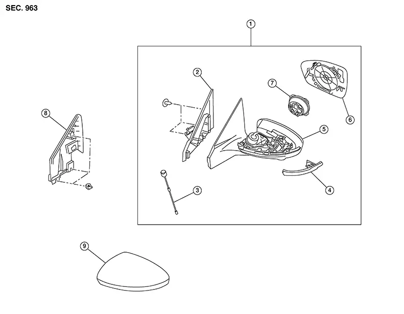
|
1. |
Door mirror assembly |
2. |
Door mirror base cover |
3. |
Side camera |
|
4. |
Door mirror turn signal lamp |
5. |
Door mirror housing |
6. |
Glass mirror |
|
7. |
Door mirror actuator |
8. |
Door mirror corner finisher |
9. |
Door mirror cover |
Removal and Installation
Removal and Installation
Removal
Remove the side camera. Refer to Removal and Installation.
Remove
screw (A) from the door mirror turn signal lamp (1). 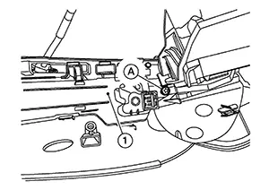
Release the
pawls on door mirror turn signal lamp (1). 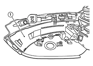
|
|
: Pawl |

Disconnect the harness connector and remove the door mirror turn signal lamp.
Installation
Installation is in the reverse order of removal.
Bulb Replacement
Bulb Replacement
The door mirror turn signal lamp bulb is LED and is serviced as an assembly to the door mirror turn signal lamp. Refer to Removal and Installation.
High-Mounted Stop Lamp
Exploded View
Exploded View

|
1. |
High-mounted stop lamp |
|
Clip |
|
Metal clip |
|
|
Front |


Removal and Installation
Removal and Installation
Removal
Slide
high-mounted stop lamp (1) rearward on parcel shelf to provide
clearance for front tabs (A). 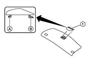
Lift front of lamp assembly up and pull forward to provide clearance for rear tabs (B).
Disconnect the harness connector from the high-mounted stop lamp and remove.
Installation
Installation is in the reverse order of removal.
Bulb Replacement
Bulb Replacement
The high-mounted stop lamp bulb is LED and is serviced as an assembly to the high-mounted stop lamp. Refer to Removal and Installation.
License Plate Lamp
Exploded View
Exploded View
|
1. |
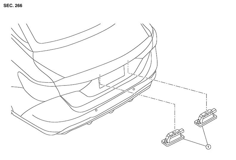
License plate lamp |
|
Clip |
Removal and Installation
Removal and Installation
REMOVAL
Using a suitable tool, release license plate lamp clip.
Disconnect the harness connector from the license plate lamp and remove the license plate lamp.
INSTALLATION
Installation is in the reverse order of removal.
Bulb Replacement
Bulb Replacement
The license plate lamp bulb is serviced as an assembly to the license plate lamp. Refer to Removal and Installation.
Rear Combination Lamp (body Side)
Exploded View
Exploded View
|
1. |
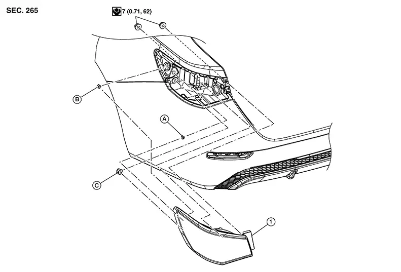
Rear combination lamp |
A. |
Grommet |
B. |
Clip |
|
C. |
Grommet |
Removal and Installation
Removal and Installation
Removal
Partially remove trunk side finisher. Refer to Removal and Installation.
Remove the rear combination lamp nuts.
Disconnect the harness connector from the rear combination lamp.
Pull the rear combination lamp rearward and remove.
Installation
Installation is the reverse order of removal.
Bulb Replacement
Bulb Replacement
Warning:
Do not touch bulb while it is lit or right after being turned off. Burning may result.
CAUTION:
-
Do not touch glass surface of the bulb with bare hands or allow oil or grease to get on it to prevent damage to bulb.
-
Do not leave the bulb out of the lamp reflector for a long time because dust, moisture, smoke, etc. may affect the performance of the lamp.
REAR TURN SIGNAL LAMP BULB
Removal
Remove the rear combination lamp. Refer to Removal and Installation.
Rotate the rear turn signal lamp bulb socket counterclockwise and remove.
Remove the rear turn signal lamp bulb from bulb socket.
Installation
Installation is in the reverse order of removal.
CAUTION:
After installing, be sure to install the bulb socket securely to ensure watertightness.
STOP/TAIL LAMP BULB
Removal
Remove the rear combination lamp. Refer to Removal and Installation.
Rotate the stop/tail lamp bulb socket counterclockwise and remove.
Remove the stop/tail lamp bulb from bulb socket.
Installation
Installation is in the reverse order of removal.
CAUTION:
After installing, be sure to install the bulb socket securely to ensure watertightness.
Rear Combination Lamp (trunk Lid Side)
Exploded View
Exploded View
|
1. |
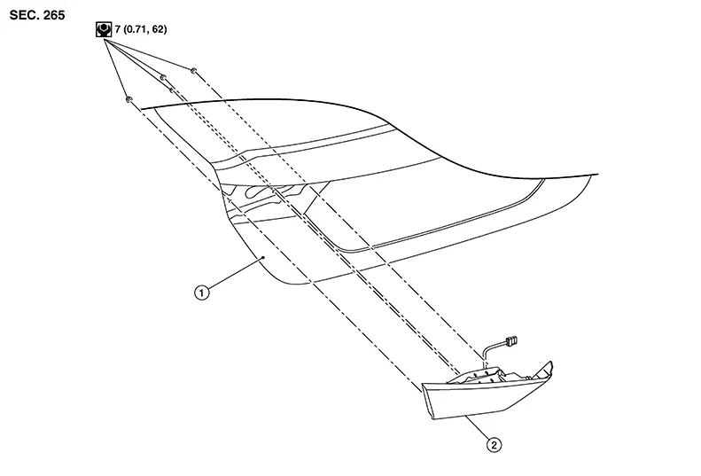
Trunk lid |
2. |
Rear combination lamp (trunk lid side) |
Removal and Installation
Removal and Installation
REMOVAL
Partially remove trunk lid trim. Refer to Removal and Installation.
Remove rear combination lamp (trunk lid side) nuts then remove rear combination lamp (trunk lid side).
INSTALLATION
Installation is in the reverse order of removal.
Combination Switch
Exploded View
Exploded View
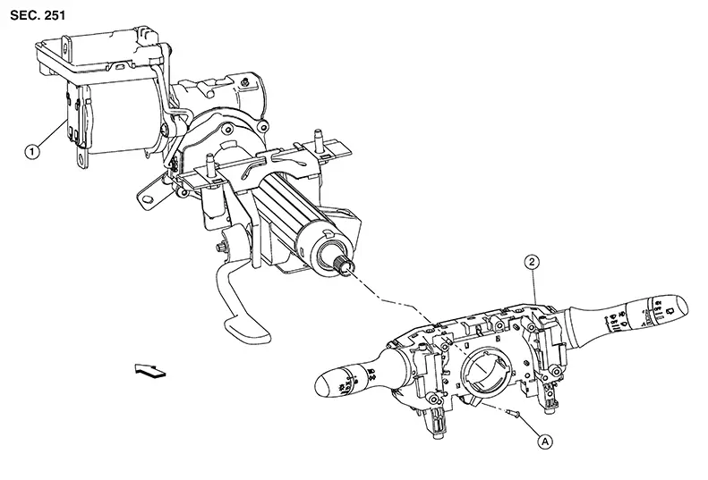
|
1. |
Steering column assembly |
2. |
Combination switch |
A. |
Screw |
|
|
Front |

Shown with the steering wheel removed for clarity only.
Removal and Installation
Removal and Installation
REMOVAL
CAUTION:
-
Do not use air or electric tools when removing or installing the combination switch.
Remove the spiral cable. Refer to Removal and Installation.
Disconnect the harness connector from the combination switch.
Remove the screw from the combination switch and remove the combination switch.
INSTALLATION
Installation is in the reverse order of removal.
CAUTION:
-
After the work is completed, make sure no system malfunction is detected by air bag warning lamp.
-
In case a malfunction is detected by the air bag warning lamp, reset with the self-diagnosis function and delete the memory with CONSULT.
-
If a malfunction is still detected after the above operation, perform self-diagnosis to repair malfunctions. Refer to Special Repair Requirement.
Hazard Switch
Exploded View
Exploded View
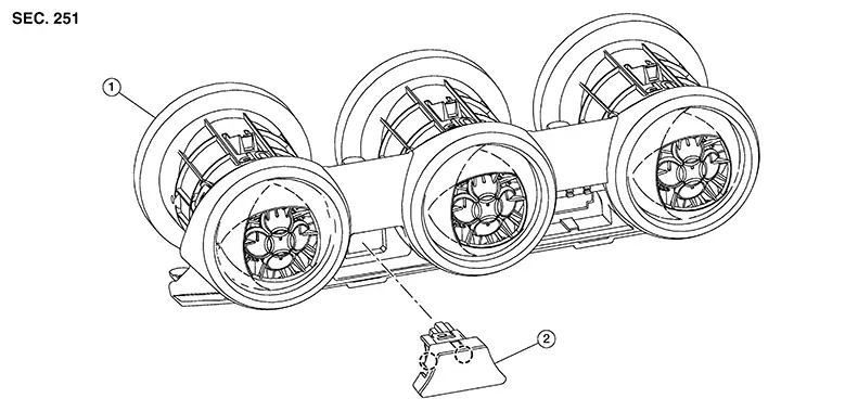
|
1. |
Center ventilator grill |
2. |
Hazard switch |
|
Pawl |
Removal and Installation
Removal and Installation
REMOVAL
Remove center ventilator grille (1). Refer to Removal and Installation.
Release
pawls and remove hazard switch (2). 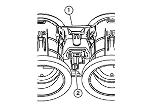
|
|
: Pawl |
INSTALLATION
Installation is in the reverse order of removal.
Optical Sensor
Exploded View
Exploded View
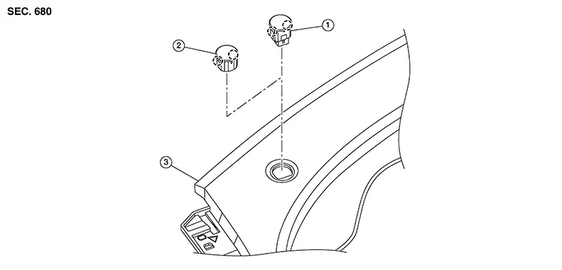
|
1. |
Optical sensor |
2. |
Mask |
3. |
Instrument panel assembly |
|
|
Pawl |
Removal and Installation
Removal and Installation
REMOVAL
Using a suitable tool, release the optical sensor from the instrument panel assembly.
Disconnect the harness connector from the optical sensor.
INSTALLATION
Installation is in the reverse order of removal.
Other materials:
P1197 Out of Gas
Dtc Description
DTC Description
This diagnosis result is detected when the fuel level of the fuel
tank is extremely low and the engine does not run normally.
DTC DETECTION LOGIC
DTC
...
Door Lock and Unlock Switch
Driver Side
Component Function Check
Component Function
Check
CHECK FUNCTION
CONSULT
Ignition switch ON.
Select ″CDL LOCK SW″, ″CDL UNLOCK SW″ in ″Data
...
Seats
This section describes the seat design and adjustment features of the Nissan
Sentra, helping drivers and passengers achieve a safe, comfortable, and ergonomically
correct seating position.
WARNING
Do not ride in a moving Nissan Sentra when the seatback is reclined.
This is extremely ...