Nissan Sentra B18 (2020-2025) Service Manual: Removal and Installation
Warning:
-
Before servicing the SRS, place the ignition switch in the OFF position, disconnect both battery terminals and wait at least three minutes.
-
Always work from the side of air bag module. Do not work in front of it.
-
Do not use air tools or electric tools for servicing.
REMOVAL
Disconnect the negative and positive battery terminals, then wait at least three minutes. Refer to Battery Disconnect.
Remove the headlining. Refer to Removal and Installation.
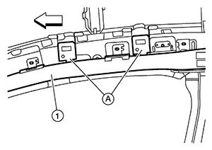
Disconnect the harness connector
(A) from the side curtain air bag module (1).
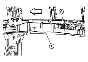
|
|
: Front |

RH side shown, LH side similar
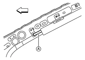
CAUTION:
-
For removing/installing the side curtain air bag module harness connector, insert a thin screwdriver wrapped in tape into the notch, lift the lock and remove the harness connector as shown.
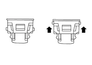
-
Install the harness connector with the lock raised, and push the lock into the harness connector as shown.
-
After installing the harness connector, check that the lock is pushed in securely.
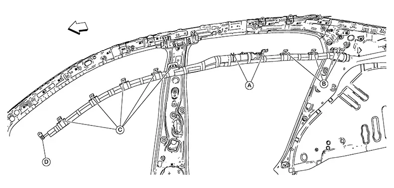
Remove bolts and the side curtain
air bag module in the order shown: Remove air bag strap bracket
(A) from the body slot. Remove front pillar brackets
(B) from the body slots. Remove the rear pillar brackets
(C) from the body slots. Remove the side curtain air bag
module brackets (D) from the body slots. 
|
|
: Front |
RH side shown, LH side similar
CAUTION:
-
Replace the side curtain air bag module if it has been dropped or sustained an impact.
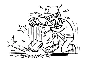
-
Do not strike the side curtain air bag module.
-
Do not insert any foreign objects (screwdriver, etc.) into the side curtain air bag module.
-
Do not disassemble the side curtain air bag module.
-
Do not expose the side curtain air bag module to temperatures exceeding 90°C (194°F).
-
Do not allow oil, grease, detergent or water to come in contact with the side curtain air bag module.
Remove bolts (A) and remove the
B pillar bracket (1). 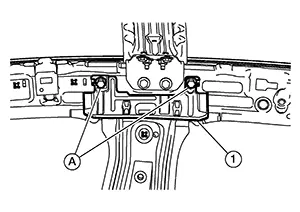
INSTALLATION
CAUTION:
-
Do not twist side curtain air bag module during installation.
-
Make sure that the anti-twist stripe is visible along entire length of the side curtain air bag module.
-
Make sure the side curtain air bag module (1) is set below the assist grip bracket (A).
Note:
: Front
RH side shown, LH side similar
-
Do not jam the front tether strap (A) when installing the front pillar finisher.
Note:: Front
RH side shown, LH side similar
-
Do not damage the harness while installing the side curtain air bag module.
-
After installation is complete, check that no system malfunction is detected causing the air bag warning lamp to illuminate.
-
If a malfunction is indicated by the air bag warning lamp after repair or replacement of the malfunctioning parts, perform the SRS final check. Refer to SRS Final Check.
Install the B pillar bracket (1)
to the body slots and tighten bolts (A) to specification.
|
B pillar bracket bolts |
:8.0 N·m (0.82 kg-m, 71 in-lb) |
Install the side curtain air bag module in the following order:
-
Install the side curtain air bag module bracket (A) to the body slots.
-
Install the rear pillar brackets (B) to the body slots.
-
Install the front pillar bracket (C) to the body slot.
-
Install bolts and tighten to specification [except air bag strap bracket (D)].
Side curtain air bag bracket bolts
:8.0 N·m (0.82 kg-m, 71 in-lb)
-
Install the side curtain air bag strap (D) bolt and tighten to specification.
Side curtain air bag strap bolt
:8.0 N·m (0.82 kg-m, 71 in-lb)
-
Connect the harness connector to the side curtain air bag module.
Note:: Front
RH side shown, LH side similar
Installation of the remaining components is in the reverse order of removal.
 Exploded View
Exploded View
1.
Side curtain air bag
bracket
...

Other materials:
Main line between ipdm-e and dlc circuit
Diagnosis procedure
1.Check connector
Turn the ignition switch off.
Disconnect the battery cable from the negative terminal.
Check the following terminals and connectors for damage, bend and loose
connection (connector side
and harness side).
Harness connector e4
Harness connec ...
Positive Crankcase Ventilation
Positive Crankcase Ventilation : Periodic Maintenance
POSITIVE CRANKCASE VENTILATION : Periodic Maintenance
Start engine and let it idle.
Replace PCV valve from the rocker cover.
Refer to Removal and Installation.
Connect PCV valve to PCV hose.
Block and unblock the air hole of ...
Unbalance steering wheel turning force and return between right
and left
Description
Unbalance steering wheel turning force and return between right
and left.
Diagnosis Procedure
1.CHECK THE ILLUMINATION OF THE EPS WARNING LAMP
Check the EPS warning lamp while engine is running.
Does the EPS warning lamp turn OFF?
YES >> GO TO 2.
NO >> Refer to S ...
