Nissan Sentra Service Manual: Unbalance steering wheel turning force and return between right and left
Description
Unbalance steering wheel turning force and return between right and left.
Diagnosis Procedure
1.CHECK THE ILLUMINATION OF THE EPS WARNING LAMP
Check the EPS warning lamp while engine is running.
Does the EPS warning lamp turn OFF? YES >> GO TO 2.
NO >> Refer to STC-33, "Diagnosis Procedure".
2.CHECK WHEEL ALIGNMENT
-
Check the wheel alignment. Refer to FSU-6, "Inspection".
-
Perform EPS self-diagnosis.
Is the inspection result normal? YES >> GO TO 3.
NO >> Adjustment of wheel alignment. Refer to FSU-6, "Inspection".
3.Check EPS control unit signal
 With CONSULT
-
Start the engine.
CAUTION:
Never drive the vehicle.
-
Turn steering wheel from full left stop to full right stop.
-
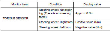
Select DATA MONITOR of EPS and select TORQUE SENSOR.
-
Perform the torque sensor inspection.
Is the inspection result normal? YES >> GO TO 5.
NO >> GO TO 4.
4.CHECK EPS MOTOR
Perform the trouble diagnosis of EPS motor. Refer to STC-27, "Diagnosis Procedure".
Is the inspection result normal? YES >> GO TO 5.
NO >> Repair or replace the specific malfunctioning part.
5.CHECK STEERING WHEEL TURNING FORCE
Check the steering wheel turning force. Refer to ST-5, "Inspection".
Is the inspection result normal? YES >> Inspection End.
NO >> Check the steering wheel turning force for mechanical malfunction. Refer to ST-5, "Inspection".
 Steering wheel turning force is heavy or light
Description
Steering wheel turning force is heavy or light.
Diagnosis Procedure
1.PERFORM SELF-DIAGNOSIS
With CONSULT
Turn the ignition switch OFF to ON.
Perform EPS self-diagnosis.
...
 Unbalance steering wheel turning force (torque variation)
Description
Unbalance steering wheel turning force (torque variation).
Diagnosis Procedure
1.PERFORM SELF-DIAGNOSIS
With CONSULT
Turn the ignition switch OFF to ON.
Perform EPS self- ...
Other materials:
Precaution
Precaution for supplemental restraint system (srs)
"air bag" and "seat belt pre-tensioner"
The Supplemental Restraint System such as “AIR BAG” and “SEAT BELT
PRE-TENSIONER”, used along
with a front seat belt, helps to reduce the risk or severity of injur ...
How to use this manual
How to use this section
Information
“Can” of lan section describes information peculiar to a vehicle and
inspection procedures.
For trouble diagnosis procedure, refer to lan-16, "trouble diagnosis
flow chart" of “can fundamental”.
Abbreviation list
Unit ...
Service Notice and Precautions for EPS System
Check the following item when performing the trouble
diagnosis.
Check any possible causes by interviewing the symptom and
it′s condition from the customer if any malfunction,
such as EPS warning lamp is turned ON, occurs.
Check if air pressure and size of tires are proper, t ...
