Nissan Sentra B18 (2020-2025) Service Manual: Removal and Installation
REMOVAL
For M/T models, drain the M/T oil. Refer to Draining.
Remove disc brake rotor. Refer to Removal and Installation.
CAUTION:
Do not depress the brake pedal while the brake caliper is removed.
Remove the wheel sensor bolt. Position the wheel sensor and the wheel sensor harness aside. Refer to Removal and Installation.
CAUTION:
Do not pull or twist the harness when removing.
Using hammer (A) and Tool (B) release staked area (C) of wheel hub lock nut (D).
|
Tool number (B) |
: (NI-52982) |
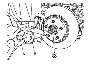
Visually verify that staked area
(A) of wheel hub lock nut (B) is completely released from front drive
shaft (1) or damage to drive shaft can occur.
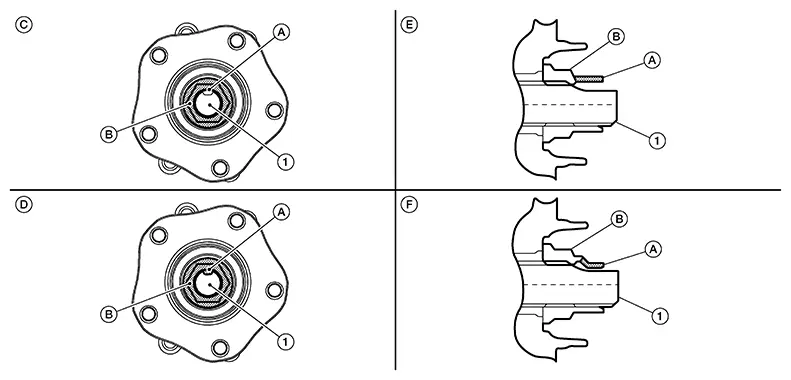
|
(C) |
: Fully released |
|
(D) |
: Not fully released |
|
(E) |
: Fully released (sectional view) |
|
(F) |
: Not fully released (sectional view) |
Warning:
To avoid risk of death or severe personal injury:
-
Be sure that staked area of wheel hub lock nut is fully released or damage to drive shaft can occur.
-
Do not damage front drive shaft threads.
Hold the wheel hub and bearing using
Tool (A). Loosen the wheel hub lock nut.
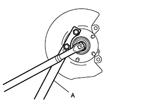
|
Tool (A) number |
: KV4014000 ( — ) |
Warning:
To avoid risk of death or severe personal injury:
-
Do not use power tool.
-
Do not damage front drive shaft threads.
-
Do not reuse drive shaft lock nut.
-
When loosening lock nut, if it does not turn smoothly, verify that staked area is completely released.
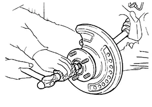
Using a piece of wood and a suitable
tool, tap on the wheel hub lock nut to disengage the drive shaft from
the wheel hub and bearing.
CAUTION:
-
Do not place the drive shaft joint at an extreme angle. Also be careful not to overextend slide joint.
-
Do not allow the drive shaft to hang down without support.

Use a suitable puller if the drive shaft cannot be separated from the wheel hub and bearing even after performing the above procedure.
Remove the wheel hub lock nut.
Remove the nut and bolt from the lower ball joint. Disconnect the steering knuckle from the transverse link.
Remove the drive shaft from the wheel hub and bearing.
Remove the wheel hub and bearing from the steering knuckle. Refer to Removal and Installation.
Remove upper pinch bolt and nut from steering knuckle.
CAUTION:
Do not reuse the upper pinch nut.
Remove the lower nut and bolt from the steering knuckle. Separate the transverse link from the steering knuckle. Refer to Exploded View.
Remove the nut and separate the outer socket from the steering knuckle. Refer to Exploded View.
Separate steering knuckle from coil spring and strut. Refer to Removal and Installation.
Remove the steering knuckle.
Perform inspection after removal. Refer to Inspection.
INSTALLATION
Installation is in the reverse order of the removal.
CAUTION:
-
Do not reuse upper pinch nut.
-
Do not reuse the lower strut pinch nut.
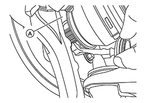
-
Apply a moderate coat of paste [service parts (440037S000)] to bearing surface (A) as shown.
 Note:
Note:
Always check with the Parts Department for the latest parts information.
-
Tighten wheel hub lock nut to specification. Refer to Exploded View.
-
Perform inspection after installation. Refer to Inspection.
 Exploded View
Exploded View
1.
Steering knuckle
2.
...
 Inspection
Inspection
INSPECTION AFTER REMOVAL
Check the following items, and replace the part
if necessary.
Check components for deformation, cracks, and
other damage.
...
Other materials:
Door mirror
Exploded view
Door mirror cover
(with side turn signal lamp)
Door mirror housing
Door mirror actuator
Glass mirror
Door mirror cover
(without side turn signal lamp)
: Pawl
Door mirror assembly
Door mirror assembly : removal and installation
Removal
Caution:
Be careful no ...
Preparation
Special Service Tools
Special Service Tools
The actual shape of the tools may differ from those
illustrated here.
Tool number
(TechMate No.)
Tool name
Description
...
How to select the cruise control mode
Selecting the vehicle-to-vehicle distance control mode: To activate the vehicle-to-vehicle
distance control mode (1) on the Nissan Sentra, briefly push and release the ICC
switch (A). This mode enables adaptive control based on surrounding traffic.
Selecting the conventional (fixed speed) c ...
