Nissan Sentra Service Manual: Removal and installation
Generator
Exploded view
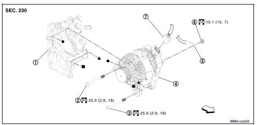
- Thermostat housing
- Generator bolt (upper)
- Generator bolt (lower)
- Generator
- B” terminal harness
- “B” terminal nut
- Generator harness connector
 Front
Front
Removal and installation
Note:
When removing components such as hoses,tubes\lines,etc,cap or plug openings to prevent fluid from spilling.
Removal
- Disconnect the battery negative terminal. Refer to PG-50, "Removal and Installation (Battery)".
- Remove cooling fan. Refer to CO-17, "Removal and Installation".
- Remove drive belt. Refer to em-15, "removal and installation".
- Disconnect generator harness connector.
- Remove “B” terminal nut, and then disconnect “B” terminal harness.
- Remove generator bolt (upper).
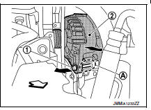
- Completely loosen generator bolt (lower) (1), and pull it out until the bolt head is in contact with the side member. And then, remove the generator (2) by pulling it forward.
 : Front
Note:
The generator can be removed together with the bolts by pulling it forward and using the thermostat housing bolt hole cutout (a).
- Remove generator upward from the vehicle.
Installation
- Installation is in the reverse order of removal.
- Refill engine coolant. Refer to co-12, "changing engine coolant".
Caution:
- Temporarily tighten the generator bolts in order from the lower to the upper, and then tighten them in order from the upper to the lower.
- For the generator, the front side (pulley side) surface is the reference surface. Fit the reference surface to the generator mounting part, and then tighten the bolts.
- Be careful to tighten “b” terminal nut carefully.
- For this model, the power generation voltage variable control system that controls the power generation voltage of the generator has been adopted. Therefore, the power generation voltage variable control system operation inspection should be performed after replacing the generator, and then make sure that the system operates normally. Refer to chg-8, "system description".
Inspection
Generator pulley inspection
Perform the following.
- Make sure that generator pulley does not rattle.
- Make sure that generator pulley nut is tight.
Note:
Replace generator as an assembly if necessary.
 Symptom diagnosis
Charging system
Symptom table
...
 Service data and specifications (SDS)
Generator
*: Always check with the parts department for the latest parts information. ...
Other materials:
Basic inspection
Diagnosis and repair work flow
Work flow
Detailed flow
1.Obtain information about symptom
Interview the customer to obtain as much information as possible about the
conditions and environment under
which the malfunction occurs.
>> GO TO 2.
2.Check symptom
Check the symptom based ...
B0028 Side airbag module RH
Description
DTC B0028 FRONT RH SIDE AIR BAG MODULE
The front RH side air bag module is wired to the air bag diagnosis sensor
unit. The air bag diagnosis sensor
unit will monitor for opens and shorts in detected lines to the front RH side
air bag module.
PART LOCATION
Refer to SRC-5, " ...
Unbalance steering wheel turning force (torque variation)
Description
Unbalance steering wheel turning force (torque variation).
Diagnosis Procedure
1.PERFORM SELF-DIAGNOSIS
With CONSULT
Turn the ignition switch OFF to ON.
Perform EPS self-diagnosis.
Is any DTC detected?
YES >> Check the DTC. Refer to STC-14, "DTC Index&quo ...
