Nissan Sentra Service Manual: Refrigerant pressure sensor
Component Function Check
1.CHECK REFRIGERANT PRESSURE SENSOR OVERALL FUNCTION
- Start engine and warm it up to normal operating temperature.
- Turn A/C switch and blower fan switch ON.
- Check the voltage between ECM harness connector terminals.
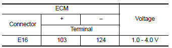
Is the inspection result normal? YES >> INSPECTION END
NO >> Proceed to EC-465, "Diagnosis Procedure".
Diagnosis Procedure
1.CHECK REFRIGERANT PRESSURE SENSOR POWER SUPPLY
- Turn ignition OFF.
- Disconnect refrigerant pressure sensor harness connector.
- Turn ignition switch ON.
- Check the voltage between refrigerant pressure sensor harness connector and ground.
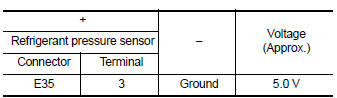
Is the inspection result normal? YES >> GO TO 3.
NO >> GO TO 2.
2.CHECK REFRIGERANT PRESSURE SENSOR POWER SUPPLY CIRCUIT
- Turn ignition switch OFF.
- Disconnect ECM harness connector.
- Check the continuity between refrigerant pressure sensor harness connector and ECM harness connector.
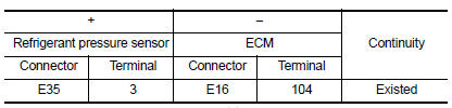
- Also check harness for short to ground.
Is the inspection result normal? YES >> Perform the trouble diagnosis for power supply circuit.
NO >> Repair or replace error-detected parts.
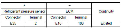
3.CHECK REFRIGERANT PRESSURE SENSOR GROUND
- Turn ignition switch OFF.
- Disconnect ECM harness connector.
- Check the continuity between refrigerant pressure sensor harness connector and ECM harness connector.
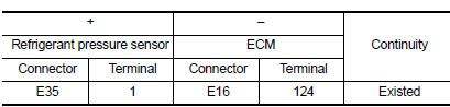
- Also check harness for short to power.
Is the inspection result normal? YES >> GO TO 4.
NO >> Repair or replace error-detected parts.
4.CHECK REFRIGERANT PRESSURE SENSOR INPUT SIGNAL CIRCUIT
- Check the continuity between ECM harness connector and refrigerant pressure sensor harness connector.
- Also check harness for short to ground and to power.
Is the inspection result normal? YES >> GO TO 5.
NO >> Repair or replace error-detected parts.
5.CHECK INTERMITTENT INCIDENT
Check intermittent incident. Refer to GI-39, "Intermittent Incident".
Is the inspection result normal? YES >> Replace refrigerant pressure sensor. Refer to HAC-110, "Removal and Installation" (For automatic air condittioner), or HAC-191, "Removal and Installation" (For manual air condittioner).
NO >> Repair or replace error-detected parts.
 Cooling fan
Component Function Check
1.CHECK COOLING FAN FUNCTION
With CONSULT
Turn ignition switch ON.
Perform “FAN” in “ACTIVE TEST” mode of “ENGINE” using CONSULT
Check ...
 Malfunction indicator lamp
Component Function Check
1.CHECK MIL FUNCTION
Turn ignition switch ON.
Check that MIL lights up.
Is the inspection result normal?
YES >> INSPECTION END
NO >> Proceed to EC-467, ...
Other materials:
Connecting procedure
NOTE:
The connecting procedure must be performed
when the vehicle is stationary. If the
vehicle starts moving during the procedure,
the procedure will be cancelled.
To connect a phone to the Bluetooth® Hands-
Free Phone System:
Press the SETTING button.
Use the TUNE/FOLDER knob to s ...
Precaution for Supplemental Restraint System (SRS) "AIR BAG" and "SEAT
BELT PRE-TENSIONER"
The Supplemental Restraint System such as “AIR BAG” and “SEAT BELT PRE-TENSIONER”,
used along
with a front seat belt, helps to reduce the risk or severity of injury to the
driver and front passenger for certain
types of collision. Information necessary to service the system ...
Both side headlamps (lo) are not
turned on
Description
The headlamps (both sides) do not turn on in any lighting switch setting.
Diagnosis Procedure
1.Check combination switch (lighting and turn signal switch)
Check the combination switch (lighting and turn signal switch). Refer to
BCS-72, "Symptom Table" (with Intelligent
...
