Nissan Sentra Service Manual: Rear shock absorber
Exploded View
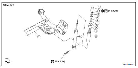
- Rear suspension beam
- Shock absorber
- Bound bumper
- Bound bumper cover
- Washer
- Bushing
- Distance tube
- Bushing
- Washer
- Piston rod lock nut
- Cap
 Front
Front
Removal and Installation
REMOVAL
- Remove the rear shock tower access flap.
- Remove the cap from the rear shock absorber.
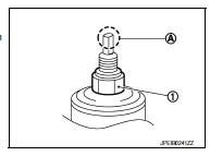
- Remove the piston rod lock nut (1).
NOTE:
To loosen the piston rod lock nut, hold the tip (A) of the piston rod.
- Remove the washer and the bushing.
- Set a suitable jack under the rear suspension beam.
CAUTION:
- At this step, the jack must be set only for supporting the removal procedure. For details on jacking up the vehicle, refer to GI-31, "Garage Jack and Safety Stand and 2-Pole Lift".
- Do not damage the rear suspension beam with the jack.
- Make sure the rear suspension beam is stable when using the jack.
- Remove the lower shock absorber bolt.
- Remove the rear shock absorber.
- Remove the bushing, the distance tube, the washer, the bound bumper cover, and the bound bumper from the shock absorber.
- Inspect the components. Refer to RSU-10, "Inspection".
INSTALLATION
Installation is in the reverse order of removal.
- To install the bushings (1), securely insert the protrusion (A) into the hole in the vehicle body.
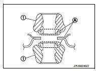
- Install the washer (1) in the direction shown.
 : Bushing side
- Perform the final tightening of the bolts and nuts under unladen conditions with the tires on level ground.
- Hold the tip (A) of the piston rod. Tighten the piston rod lock nut (1) to the specification.
CAUTION:
Do not reuse the piston rod lock nut.
- When installing the cap, securely engage the cap groove (A) with the flange on the vehicle body.
- After replacing the shock absorber, always follow the disposal procedure
to discard the old shock absorber.
Refer to RSU-10, "Disposal".
Inspection
INSPECTION AFTER REMOVAL
Shock Absorber
Check the following items and replace the parts if necessary.
- Check the shock absorber for oil leaks, deformation, cracks, and other damage.
- Check the piston rod for damage, uneven wear, and distortion.
Bound Bumper, Bushing
Check for cracks and damage. Replace the parts if necessary.
Washer, Bound Bumper Cover, Distance Tube
- Check for cracks and damage. Replace the parts if necessary.
Disposal
- Set the shock absorber horizontally with the piston rod fully extended.
- Drill a 2 – 3 mm (0.08 – 0.12 in) hole at the position (

) from the top as shown to release gas gradually.
CAUTION:
- Wear eye protection (safety glasses).
- Wear gloves.
- Be careful with metal chips or oil blown out by the compressed gas.
NOTE:
- Drill vertically in this direction (

). - Drill directly to the outer tube avoiding brackets.
- The gas is clear, colorless, odorless, and harmless.
(A) : 20 – 30 mm (0.79 – 1.18 in)
- Position the drilled hole downward and drain oil by moving the piston rod several times.
CAUTION:
Dispose of drained oil according to the law and local regulations.

 Coil spring
Exploded View
Upper rubber seat
Coil spring
Lower rubber seat
Rear suspension beam
Front
Removal and Installation
REMOVAL
Set a suitable jack under the rear suspension beam.
...
Other materials:
P014C, P014D, P015A, P015B A/F Sensor 1
DTC Logic
DTC DETECTION LOGIC
To judge the malfunction of A/F sensor 1, this diagnosis measures response
time of the A/F signal computed
by ECM from the A/F sensor 1 signal. The time is compensated by engine operating
(speed and load), fuel
feedback control constant, and the A/F sensor 1 tem ...
Headlining
Exploded View
STANDARD ROOF
Headlining
Assist grip
Map lamp bracket
Sun visor (RH)
Sun visor cover
Sun visor holder
Map lamp
Sun visor (LH)
Interior room lamp
Assist grip cap
Headlining clip
Metal clip
Pawl
Metal clip
Sunroof
Headlining
Assist grip
...
Rapid air pressure loss
Rapid air pressure loss or a “blow-out” can occur
if the tire is punctured or is damaged due to
hitting a curb or pothole. Rapid air pressure loss
can also be caused by driving on under-inflated
tires.
Rapid air pressure loss can affect the handling
and stability of the vehicle, especially ...
