Nissan Sentra Service Manual: Power supply and ground circuit
Diagnosis procedure
Regarding wiring diagram information, refer to bcs-51, "wiring diagram".
1.Check fuses and fusible link
Check that the following fuses and fusible link are not blown.
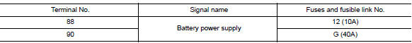
Is the fuse blown? YES >> Replace the blown fuse or fusible link after repairing the affected circuit.
NO >> GO TO 2.
2.Check power supply circuit
- Disconnect bcm connector m85.
- Check voltage between bcm connector m85 and ground.
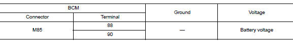
Is the inspection result normal? YES >> GO TO 3.
NO >> Repair harness or connector.
3.Check ground circuit
Check continuity between bcm connector m85 and ground.
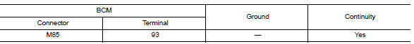
Is the inspection result normal? YES >> Inspection End.
NO >> Repair harness or connector.
Combination meter buzzer
Component function check
1.Check function
- Select intelligent key of bcm using consult.
- Select inside buzzer in active test mode.
- Touch Key, Knob or Take Out to check that it works normally.
Is the inspection result normal? Yes >> Combination meter buzzer is OK.
No >> Refer to DLK-91, "Diagnosis Procedure".
Diagnosis Procedure
1.CHECK METER BUZZER CIRCUIT
Refer to WCS-28, "Component Function Check".
Is the inspection result normal? Yes >> GO TO 2.
No >> Repair or replace harness.
2.CHECK INTERMITTENT INCIDENT
Refer to GI-39, "Intermittent Incident".
>> Inspection End.
 DTC/circuit diagnosis
U1000 CAN COMM CIRCUIT
Description
Refer to lan-7, "can communication system : system description".
Dtc logic
Dtc detection logic
Note:
U1000 can be set if a module harness was disconn ...
 Door lock actuator
Driver side
Driver side : component function check
1.CHECK FUNCTION
Select DOOR LOCK of BCM using CONSULT.
Select DOOR LOCK in ACTIVE TEST mode.
Touch ALL LOCK or ALL UNLK to check that it w ...
Other materials:
Checking bulbs
With all doors closed, apply the parking brake
and place the ignition switch in the ON position
without starting the engine. The following lights
will come on:
If equipped, the following lights come on briefly
and then go off:
If any light fails to come on, it may indicate
an open circuit ...
Trunk lid release switch
WARNING
Do not drive with the trunk lid open. This
could allow dangerous exhaust gases
to be drawn into the vehicle. See “Exhaust
gas” in the “Starting and driving”
section of this manual.
Closely supervise children when they
are around cars to prevent ...
Harness connector
Description
Harness connector (tab-locking type)
The tab-locking type connectors help prevent accidental looseness or
disconnection.
The tab-locking type connectors are disconnected by pushing or lifting
the locking tab(s). Refer to the figure
below.
Refer to the next page for desc ...
