Nissan Sentra Service Manual: Door lock actuator
Driver side
Driver side : component function check
1.CHECK FUNCTION
- Select DOOR LOCK of BCM using CONSULT.
- Select DOOR LOCK in ACTIVE TEST mode.
- Touch ALL LOCK or ALL UNLK to check that it works normally.
Is the inspection result normal? YES >> Door lock actuator is OK.
NO >> Refer to DLK-92, "DRIVER SIDE : Diagnosis Procedure".
Driver side : diagnosis procedure
Regarding Wiring Diagram information, refer to DLK-41, "Wiring Diagram".
1.Check door lock actuator input signal
- Turn ignition switch OFF.
- Disconnect front door lock actuator LH connector
- Check voltage between front door lock actuator LH harness connector and ground.
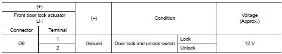
Is the inspection result normal? Yes >> replace front door lock actuator lh .
No >> go to 2.
2.Check door lock actuator circuit
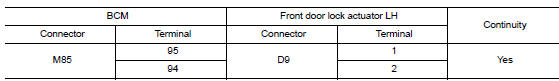
- Disconnect BCM connector and all door lock actuator connectors.
- Check continuity between bcm harness connector and front door lock actuator lh harness connector.
- Check continuity between bcm harness connector and ground.
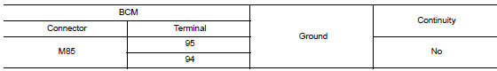
Is the inspection result normal? YES >> GO TO 3.
NO >> Repair or replace harness.
3.Check bcm output signal
- Connect bcm connector.
- Check voltage between front door lock actuator lh harness connector and ground.
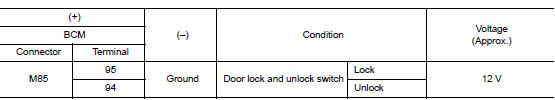
Is the inspection result normal? Yes >> check for internal short of each door lock actuator.
No >> replace bcm. Refer to bcs-73, "removal and installation".
Passenger side
Passenger side : component function check
1.Check function
- Select DOOR LOCK of BCM using CONSULT.
- Select DOOR LOCK in ACTIVE TEST mode.
- Touch all lock or all unlk to check that it works normally.
Is the inspection result normal? Yes >> door lock actuator is ok.
No >> refer to dlk-93, "passenger side : diagnosis procedure".
Passenger side : diagnosis procedure
Regarding wiring diagram information, refer to dlk-41, "wiring diagram".
1.Check door lock actuator input signal
- Turn ignition switch OFF.
- Disconnect front door lock actuator rh connector.
- Check voltage between front door lock actuator RH harness connector and ground.
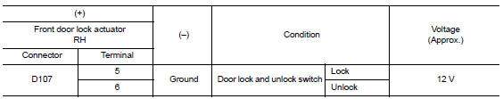
Is the inspection result normal? YES >> Replace front door lock actuator (RH).
NO >> GO TO 2.
2.Check door lock actuator circuit
- Disconnect bcm connector and all door lock actuators.
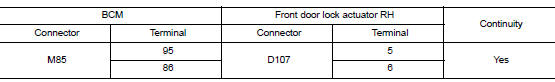
- Check continuity between bcm harness connector and front door lock actuator rh harness connector.
- Check continuity between bcm harness connector and ground.
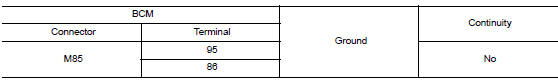
Is the inspection result normal? Yes >> go to 3.
No >> repair or replace harness.
3.Check bcm output signal
- Connect bcm connector.
- Check voltage between front door lock actuator rh harness connector and ground.
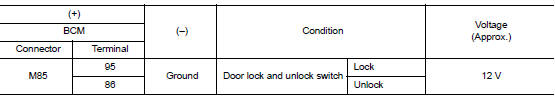
Is the inspection result normal? Yes >> check for internal short of each door lock actuator.
No >> replace bcm. Refer to bcs-73, "removal and installation".
Rear lh
Rear lh : component function check
1.Check function
- Select door lock of bcm using consult.
- Select DOOR LOCK in ACTIVE TEST mode.
- Touch all lock or all unlk to check that it works normally.
Is the inspection result normal? Yes >> door lock actuator is ok.
No >> refer to dlk-94, "rear lh : diagnosis procedure".
Rear lh : diagnosis procedure
Regarding Wiring Diagram information, refer to DLK-41, "Wiring Diagram".
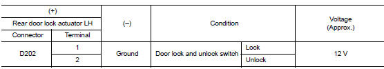
1.Check door lock actuator input signal
- Turn ignition switch off.
- Disconnect rear door lock actuator lh connector.
- Check voltage between rear door lock actuator lh harness connector and ground.
Is the inspection result normal? Yes >> replace rear door lock actuator lh.
No >> go to 2.
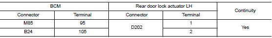
2.Check door lock actuator circuit
- Disconnect bcm connector and all door lock actuator connectors.
- Check continuity between bcm harness connector and rear door lock actuator lh harness connector.
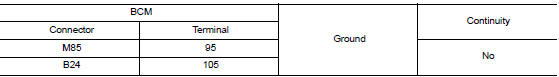
- Check continuity between bcm harness connector and ground.
Is the inspection result normal? YES >> GO TO 3.
NO >> Repair or replace harness.
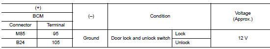
3.Check bcm output signal
- Connect BCM connector.
- Check voltage between rear door lock actuator LH harness connector and ground.
Is the inspection result normal? Yes >> check for internal short of each door lock actuator.
No >> replace bcm. Refer to bcs-73, "removal and installation".
Rear RH
REAR RH : Component Function Check
1.Check function
- Select door lock of bcm using consult.
- Select door lock in active test mode.
- Touch all lock or all unlk to check that it works normally.
Is the inspection result normal? Yes >> door lock actuator is ok.
No >> refer to dlk-95, "rear rh : diagnosis procedure".
REAR RH : Diagnosis Procedure
Regarding wiring diagram information, refer to dlk-41, "wiring diagram".
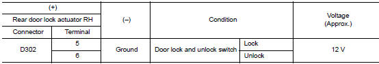
1.Check door lock actuator input signal
- Turn ignition switch off.
- Disconnect rear door lock actuator RH connector.
- Check voltage between rear door lock actuator rh harness connector and ground.
Is the inspection result normal? Yes >> replace rear door lock actuator rh.
No >> go to 2.
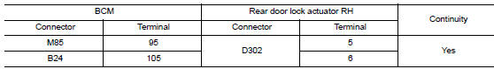
2.Check door lock actuator circuit
- Disconnect BCM connector and all door lock actuator connectors.
- Check continuity between bcm harness connector and rear door lock actuator rh harness connector.
- Check continuity between bcm harness connector and ground.
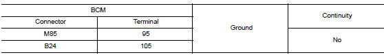
Is the inspection result normal? Yes >> go to 3.
No >> repair or replace harness.
3.Check bcm output signal
- Connect bcm connector.
- Check voltage between rear door lock actuator rh harness connector and ground.
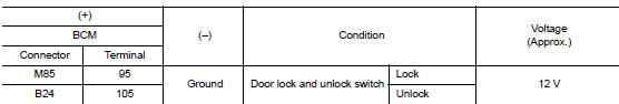
Is the inspection result normal? Yes >> check for internal short of each door lock actuator.
No >> replace bcm. Refer to bcs-73, "removal and installation".
 Power supply and ground circuit
Diagnosis procedure
Regarding wiring diagram information, refer to bcs-51, "wiring diagram".
1.Check fuses and fusible link
Check that the following fuses and fusible link are not blown.
...
 Door lock and unlock switch
Component function check
1.Check function
Select door lock of bcm using consult.
Select cdl lock sw, cdl unlock sw in data monitor mode.
Check that the function operates normally according to ...
Other materials:
Driver side power window does not operate
Diagnosis Procedure
1.Check front power window motor (driver side)
Check front power window motor (driver side).
Refer to pwc-43, "driver side : diagnosis procedure".
Is the inspection result normal?
Yes >> go to 2.
No >> repair or replace the malfunctioning parts.
...
Basic inspection
DIAGNOSIS AND REPAIR WORKFLOW
Work Flow
DETAILED FLOW
1.LISTEN TO CUSTOMER COMPLAINT
Listen to customer complaint. Get detailed information about the conditions
and environment when the symptom
occurs.
>> GO TO 2.
2.VERIFY THE SYMPTOM WITH OPERATIONAL CHECK
Verify the symptom with ...
P2127, P2128 APP Sensor
DTC Logic
DTC DETECTION LOGIC
DTC No.
CONSULT screen terms
(Trouble diagnosis content)
DTC detecting condition
Possible cause
P2127
APP SEN 2/CIRC
(Throttle/Pedal position
sensor/switch “E” circuit
low)
An excessively low voltage from the APP
...
