Nissan Sentra Service Manual: Door lock and unlock switch
Component function check
1.Check function
- Select door lock of bcm using consult.
- Select cdl lock sw, cdl unlock sw in data monitor mode.
- Check that the function operates normally according to the following conditions.
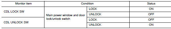
Is the inspection result normal? YES >> Main power window and door lock/unlock switch is OK.
NO >> Refer to DLK-97, "Diagnosis Procedure".
Diagnosis procedure
Regarding Wiring Diagram information, refer to DLK-41, "Wiring Diagram".
1.Check door lock and unlock switch input signal
- Turn ignition switch off.
- Disconnect main power window and door lock/unlock switch connector.
- Check signal between main power window and door lock/unlock switch harness connector and ground using oscilloscope.
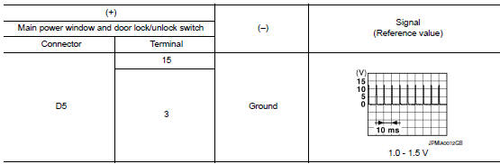
Is the inspection result normal? Yes >> go to 3.
No >> go to 2.
2.Check door lock and unlock switch circuit
- Disconnect bcm connector.
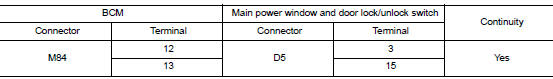
- Check continuity between bcm harness connector and main power window and door lock/unlock switch harness connector.
- Check continuity between BCM harness connector and ground.
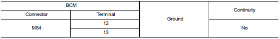
Is the inspection result normal? Yes >> replace bcm. Refer to bcs-73, "removal and installation".
No >> repair or replace harness.
3.Check door lock and unlock switch ground
Check continuity between main power window and door lock/unlock switch harness connector and ground.
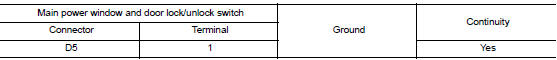
Is the inspection result normal? Yes >> go to 4.
No >> repair or replace harness.
4.Check door lock and unlock switch
Refer to dlk-98, "component inspection".
Is the inspection result normal? Yes >> go to 5.
No >> replace main power window and door lock/unlock switch. Refer to pwc-70, "removal and installation".
5.Check intermittent incident
Refer to GI-39, "Intermittent Incident".
>> Inspection End.
Component inspection
1.Check main power window and door lock/unlock switch
- Turn ignition switch off.
- Disconnect main power window and door lock/unlock switch connector.
- Check continuity between main power window and door lock/unlock switch terminals.
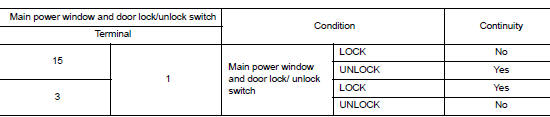
Is the inspection result normal? Yes >> inspection end
No >> replace main power window and door lock/unlock switch. Refer to pwc-70, "removal and installation".
Door request switch
Component function check
1.Check function
- Select INTELLIGENT KEY of CM using CONSULT.
- Select REQ SW-DR, REQ SW-AS in DATA MONITOR mode
- Check that the function operates normally according to the following conditions.
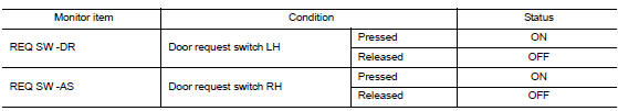
Is the inspection result normal? Yes >> front door request switch is ok.
No >> refer to dlk-100, "diagnosis procedure".
Diagnosis procedure
Regarding Wiring Diagram information, refer to DLK-49, "Wiring Diagram".
1.Check door request switch input signal
- Turn ignition switch off.
- Disconnect malfunctioning front door request switch connector.
- Check voltage between malfunctioning front door request switch harness connector and ground.
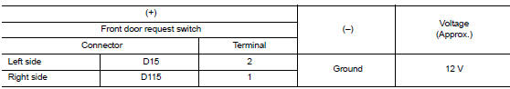
Is the inspection result normal? Yes >> go to 3.
No >> go to 2.
2.Check door request switch circuit
- Disconnect bcm connector.
- Check continuity between malfunctioning front door request switch harness connector and bcm harness connector.
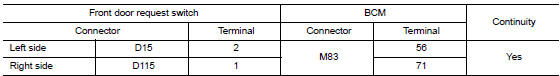
- Check continuity between malfunctioning front door request switch harness connector and ground.
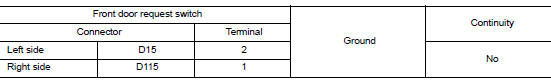
Is the inspection result normal? Yes >> go to 4.
No >> repair or replace harness.
4.Check door request switch
Refer to dlk-101, "component inspection".
Is the inspection result normal? Yes >> go to 5.
No >> replace malfunctioning front door request switch.
5.Check intermittent incident
Refer to gi-39, "intermittent incident".
>> Inspection end.
Component inspection
1.Check door request switch
- Turn ignition switch OFF.
- Disconnect malfunctioning front door request switch connector.
- Check continuity between malfunctioning front door request switch terminals.
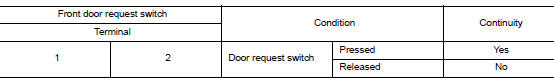
Is the inspection result normal? Yes >> inspection end.
No >> replace malfunctioning front door request switch.
Door switch
Component function check
1.Check function
- Select DOOR LOCK of BCM using CONSULT.
- Select door sw-dr, door sw-as, door sw-rl and door sw-rr in data monitor mode.
- Check that the function operates normally according to the following conditions.
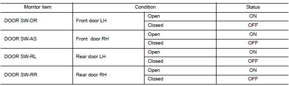
Is the inspection result normal? Yes >> door switch is ok.
No >> refer to dlk-102, "diagnosis procedure".
Diagnosis procedure
Regarding wiring diagram information, refer to dlk-49, "wiring diagram".
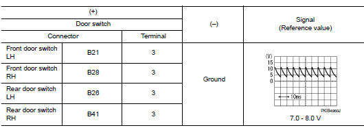
1.Check door switch input signal
- Turn ignition switch off.
- Disconnect malfunctioning door switch connector.
- Check signal between malfunctioning door switch harness connector and ground using oscilloscope.
Is the inspection result normal? Yes >> go to 3.
No >> go to 2.
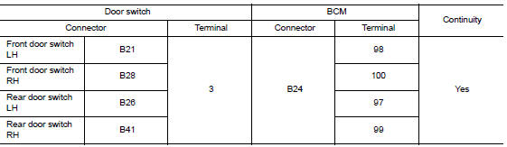
2.Check door switch circuit
- Disconnect bcm connector.
- Check continuity between door switch harness connector and bcm harness connector.
- Check continuity between door switch harness connector and ground.

Is the inspection result normal? Yes >> replace bcm. Refer to bcs-73, "removal and installation".
No >> repair or replace harness.
3.Check door switch
Refer to dlk-103, "component inspection".
Is the inspection result normal? Yes >> go to 4.
No >> replace malfunctioning door switch.
4.Check intermittent incident
Refer to gi-39, "intermittent incident".
>> Inspection end.
Component inspection
1.Check door switch
- Turn ignition switch off.
- Disconnect malfunctioning door switch connector.
- Check continuity between door switch terminals.
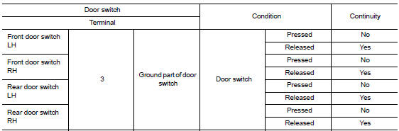
Is the inspection result normal?
Yes >> inspection end.
No >> replace malfunction door switch.
Hazard function
Component Function Check
1.CHECK FUNCTION
- Select INTELLIGENT KEY of BCM using CONSULT.
- Select FLASHER in ACTIVE TEST mode.
- Touch LH or RH to check that it works normally.
Is the inspection result normal? YES >> Hazard warning lamp circuit is OK.
NO >> Refer to DLK-105, "Diagnosis Procedure".
Diagnosis Procedure
1.CHECK HAZARD SWITCH CIRCUIT
Refer to EXL-105, "Component Function Check".
Is the inspection result normal? YES >> GO TO 2.
NO >> Repair or replace harness.
2.CHECK INTERMITTENT INCIDENT
Refer to GI-39, "Intermittent Incident".
>> Inspection End.
Intelligent key
Component function check
Note:
The signal tech ii tool (j-50190) can be used to perform the following functions. Refer to the signal tech ii user guide for additional information.
- Check intelligent key relative signal strength.
- Confirm vehicle Intelligent Key antenna signal strength.
1.Check function
- Select “INTELLIGENT KEY” of “BCM” using CONSULT.
- Select “rke ope coun1” in “data monitor” mode.
- Check that the function operates normally according to the following conditions.
| Monitor item | Condition |
| Rke ope coun1 | Check that the numerical value is changing while operating on the intelligent key. |
Is the inspection result normal? Yes >> intelligent key is ok.
No >> refer to dlk-106, "diagnosis procedure".
Diagnosis procedure
Note:
The signal tech ii tool (j-50190) can be used to perform the following functions. Refer to the signal tech ii user guide for additional information.
- Check Intelligent Key relative signal strength.
- Confirm vehicle intelligent key antenna signal strength.
1.Check intelligent key battery
Check by connecting a resistance (approximately 300ù) so that the current value becomes about 10 ma. Refer to dlk-200, "removal and installation".
Standard : approx. 2.5 - 3.0V
Is the measurement value within the specification? Yes >> replace intelligent key.
No >> replace intelligent key battery.
Key warning lamp
Component Function Check
1.Check function
- Select intelligent key of bcm using consult.
- Select indicator in active test mode.
- Touch key ind or key on to check that it works normally.
Is the inspection result normal? YES >> Key warning lamp is OK.
NO >> Refer to DLK-107, "Diagnosis Procedure".
Diagnosis Procedure
1.Check key warning lamp
Refer to DLK-31, "WARNING FUNCTION : System Description".
Is the inspection result normal? YES >> GO TO 2.
NO >> Repair or replace harness.
2.Check intermittent incident
Refer to GI-39, "Intermittent Incident".
>> Inspection End.
Remote keyless entry receiver
Component function check
1.Check function
- Select intelligent key of bcm using consult.
- Select rke ope coun1 in data monitor mode.
- Check that the function operates normally according to the following conditions.
| Monitor item | Condition |
| Rke ope coun1 | Checks whether value changes when operating intelligent key |
Is the inspection result normal? Yes >> remote keyless entry receiver is ok.
No >> refer to dlk-108, "diagnosis procedure".
Diagnosis procedure
Regarding wiring diagram information, refer to dlk-49, "wiring diagram".
1.Check remote keyless entry receiver output signal
- Turn ignition switch off.
- Check voltage between bcm harness connector and ground.
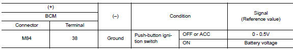
Is the inspection result normal? Yes >> replace bcm. Refer to bcs-73, "removal and installation".
No >> go to 2.
2.Check remote keyless entry receiver circuit 1
- Disconnect bcm and remote keyless entry receiver connectors.
- Check continuity between bcm harness connector and remote keyless entry receiver harness connector.
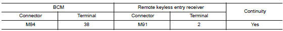
- Check continuity between bcm harness connector and ground.
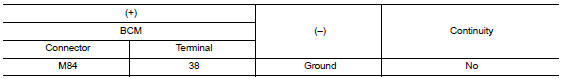
Is the inspection result normal? Yes >> go to 3.
No >> repair or replace harness.
3.Check remote keyless entry receiver power supply
Check voltage between remote keyless entry receiver harness connector and ground.
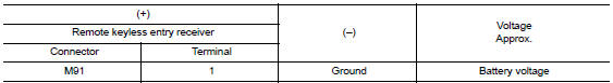
Is the inspection result normal? Yes >> go to 4.
No-1 >> check 10a fuse no. 14 [Located in fuse block j/b].
No-2 >> repair or replace harness between bcm and 10a fuse no. 14.
4.Check remote keyless entry receiver ground circuit
Check continuity between remote keyless entry receiver harness connector and ground.
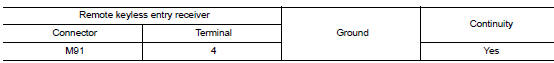
Is the inspection result normal? YES >> Replace remote keyless entry receiver. Refer to DLK-199, "Removal and Installation".
NO >> Repair or replace harness.
Shift p warning lamp
Component function check
1.Check function
- Select intelligent key of bcm using consult.
- Select LCD in ACTIVE TEST mode.
- Touch set p to check that it works normally.
Is the inspection result normal? Yes >> shift p warning lamp is ok.
No >> refer to dlk-110, "diagnosis procedure".
Diagnosis procedure
1.Check shift p warning lamp
Refer to DLK-31, "WARNING FUNCTION : System Description".
Is the inspection result normal? YES >> GO TO 2.
NO >> Repair or replace the malfunctioning parts.
2.Check intermittent incident
Refer to gi-39, "intermittent incident".
>> Inspection end.
Trunk lid opener actuator
Component Function Check
1.Check function
- Select intelligent key of bcm using consult.
- Select trunk/glass hatch in active test mode.
- Touch open to check that it works normally.
Is the inspection result normal? Yes >> trunk lid opener actuator is ok.
No >> refer to dlk-111, "diagnosis procedure".
Diagnosis Procedure
Regarding wiring diagram information, refer to dlk-63, "wiring diagram".
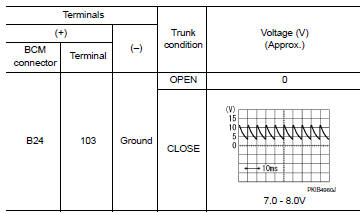
1.Check trunk lid opener input signal
- Turn ignition switch OFF.
- Disconnect trunk lid opener assembly connector.
- Check voltage between trunk lid opener assembly harness connector and ground.
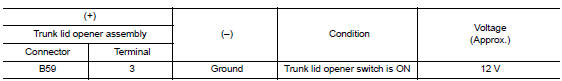
Is the inspection result normal? Yes >> go to 3.
No >> go to 2.
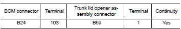
2.Check trunk lid opener actuator circuit
- Disconnect bcm connector.
- Check continuity between bcm harness connector and trunk lid opener assembly harness connector.
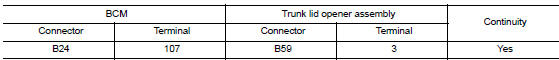
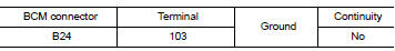
- Check continuity between bcm harness connector and ground.
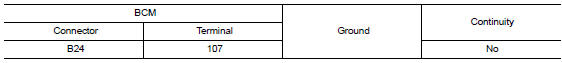
Is the inspection result normal? Yes >> replace bcm. Refer to bcs-73, "removal and installation".
No >> repair or replace harness.
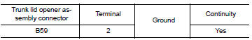
3.Check trunk lid opener actuator ground circuit
Check continuity between trunk lid opener assembly harness connector and ground.
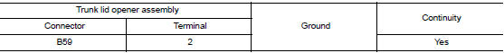
Is the inspection normal? Yes >> replace trunk lid opener assembly.
No >> repair or replace harness.
Trunk lid opener switch
Component function check
1.Check function
- Select trunk of bcm using consult
- Select TR/BD OPEN SW in DATA MONITOR mode.
- Check that the function operates normally according to the following conditions.
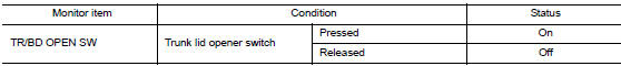
Is the inspection result normal? Yes >> trunk lid opener switch is ok.
No >> refer to dlk-113, "diagnosis procedure".
Diagnosis Procedure
Regarding wiring diagram information, refer to dlk-63, "wiring diagram".
1.Check trunk lid opener input signal
- Turn ignition switch OFF
- Disconnect trunk lid opener switch connector.
- Check signal between trunk lid opener switch harness connector and ground using oscilloscope
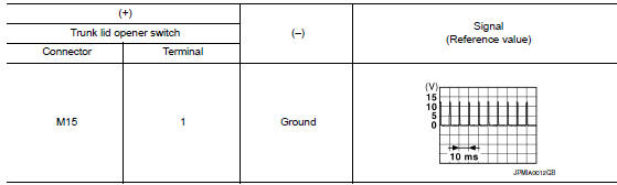
Is the inspection result normal? Yes >> go to 3.
No >> go to 2.
2.Check trunk lid opener switch circuit
- Disconnect bcm connector.
- Check continuity between bcm harness connector and trunk lid opener switch harness connector.
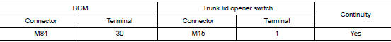
- Check continuity between bcm harness connector and ground.
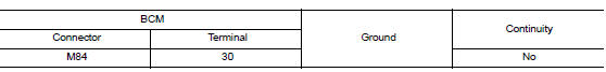
Is the inspection result normal? YES >> Replace BCM. Refer to BCS-73, "Removal and Installation".
NO >> Repair or replace harness.
3.Check trunk lid opener switch ground circuit
Check continuity between trunk lid opener switch harness connector and ground.
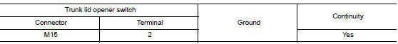
Is the inspection result normal? Yes >> go to 4.
No >> repair or replace harness.
4.Check trunk lid opener switch
Refer to DLK-113, "Component Function Check".
Is the inspection result normal? YES >> GO TO 5.
NO >> Replace trunk lid opener switch.
5.Check intermittent incident
Refer to gi-39, "intermittent incident".
>> Inspection end.
Component Inspection
1.Check trunk lid opener switch
- Turn ignition switch OFF
- Disconnect trunk lid opener switch connector
- Check continuity between trunk lid opener switch terminals.
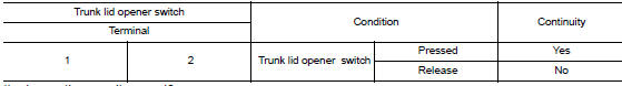
Is the inspection result normal? YES >> Inspection End.
NO >> Replace trunk lid opener switch.
Trunk lamp switch
Description
Detects trunk open/close condition.
Component Function Check
1.Check function
 With consult
Check TRNK/HAT MNTR in Data Monitor mode with CONSULT.
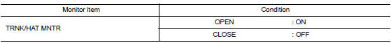
Is the inspection result normal? YES >> Trunk room lamp switch is OK.
NO >> Refer to DLK-115, "Diagnosis Procedure".
Diagnosis Procedure
Regarding Wiring Diagram information, refer to DLK-63, "Wiring Diagram".
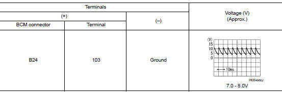
1.Check trunk lid switch input signal
- Turn ignition switch off.
- Check voltage between bcm connector and ground.
Is the inspection result normal? Yes >> go to 6
No >> go to 2
2.Check trunk room lamp switch circuit
- Disconnect bcm and trunk lid opener assembly connector.
- Check continuity between bcm connector and trunk lid opener assembly connector.
- Check continuity between bcm connector and ground.
Is the inspection result normal? Yes >> go to 3 no >> repair or replace harness between bcm and trunk lid opener assembly.
3.Check trunk lid switch ground circuit
Check continuity between trunk lid opener assembly connector and ground.
Is the inspection result normal? YES >> GO TO 4
No >> repair or replace trunk lid opener assembly ground circuit.
4.Check bcm output signal
- Ensure trunk lid remains closed during this step.
- Connect bcm connector.
- Check voltage between bcm connector and ground.
Is the inspection result normal? Yes >> go to 5
NO >> Replace BCM. Refer to BCS-73, "Removal and Installation".
5.Check trunk room lamp switch
Refer to dlk-113, "component function check".
Is the inspection result normal? Yes >> go to 6
No >> replace trunk lid opener assembly.
6.Check intermittent incident
Refer to gi-39, "intermittent incident".
>> Inspection end.
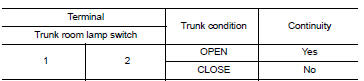
Component Inspection
1.Check trunk room lamp switch
- Turn ignition switch off
- Disconnect trunk lid opener assembly connector.
- Check trunk room lamp switch.
Is the inspection result normal? Yes >> inspection end.
No >> replace trunk lid opener assembly.
 Door lock actuator
Driver side
Driver side : component function check
1.CHECK FUNCTION
Select DOOR LOCK of BCM using CONSULT.
Select DOOR LOCK in ACTIVE TEST mode.
Touch ALL LOCK or ALL UNLK to check that it w ...
 Symptom diagnosis
Door does not lock/unlock with door lock and unlock switch
All door
ALL DOOR : Description
All doors do not lock/unlock using door lock and unlock switch.
ALL DOOR : Diagnosis Procedure
1.CHECK D ...
Other materials:
Diagnosis system (bcm)
Common item
COMMON ITEM : CONSULT Function (BCM - COMMON ITEM)
Application item
Consult performs the following functions via can communication with bcm.
Direct diagnostic mode
Description
Ecu identification
The bcm part number is displayed.
Self diagnostic result
...
NISSAN vehicle immobilizer system
The NISSAN Vehicle Immobilizer system will not
allow the engine to start without the use of the
registered key.
If the engine fails to start using a registered key
(for example, when interference is caused by
another registered key, an automated toll road
device or automatic payment device o ...
Vehicle Dynamic Control (VDC) system
The Vehicle Dynamic Control (VDC) system uses
various sensors to monitor driver inputs and vehicle
motion. Under certain driving conditions,
the VDC System helps to perform the following
functions:
Controls brake pressure to reduce wheel
slip on one slipping drive wheel so power is
trans ...
