Nissan Sentra Service Manual: Parking brake switch
Component Function Check
1.CHECK PARKING BRAKE SWITCH OPERATION
Check that brake warning lamp in combination meter turns ON/OFF when parking brake is actuated.
Is the inspection result normal? YES >> Inspection End.
NO >> Proceed to diagnosis procedure. Refer to BRC-90, "Diagnosis Procedure".
Diagnosis Procedure
Regarding Wiring Diagram information, refer to BRC-44, "Wiring Diagram".
1.CONNECTOR INSPECTION
-
Turn ignition switch OFF.
-
Disconnect combination meter and parking brake switch connectors.
-
Check connectors and terminals for deformation, disconnection, looseness or damage.
Is the inspection result normal? YES >> GO TO 2.
NO >> Repair or replace as necessary.
2.CHECK PARKING BRAKE SWITCH
Check parking brake switch. Refer to BRC-91, "Component Inspection".
Is the inspection result normal? YES >> GO TO 3.
NO >> Replace parking brake switch. Refer to PB-7, "Exploded View".
3.Check parking brake switch signal
 With CONSULT.
-
Connect combination meter connector and parking brake switch connectors.
-
Turn ignition switch ON.
-
In “DATA MONITOR” select “PARK BRAKE SW” and check parking brake switch signal.
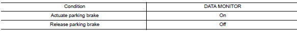
Is the inspection result normal? YES >> Refer to BRC-51, "Work Flow".
NO >> GO TO 4.
4.Check parking brake switch circuit
-
Turn ignition switch OFF.
-
Disconnect combination meter and parking brake switch connectors.
-
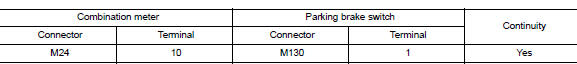
Check continuity between combination meter connector M24 terminal 10 and parking brake switch connector M130 terminal 1.
-
Check continuity between combination meter connector and ground.
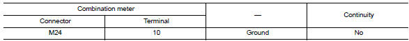
Is the inspection result normal? YES >> Replace combination meter. Refer to MWI-77, "Removal and Installation".
NO >> Repair or replace malfunctioning components.
Component Inspection
1.Check parking brake switch
-
Turn ignition switch OFF.
-
Disconnect parking brake switch connector.
-
Check continuity between parking brake switch terminal 1 and ground.
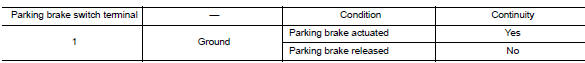
Is the inspection result normal? YES >> Inspection End.
NO >> Replace parking brake switch. Refer to PB-7, "Exploded View".
 U1010 Control unit (CAN)
Description
Initial diagnosis of ABS actuator and electric unit (control
unit)
DTC Logic
DTC DETECTION LOGIC
DTC
Items
(CONSULT screen terms)
DTC detection condition
Possible ...
 VDC OFF Switch
Component Function Check
1.CHECK VDC OFF SWITCH OPERATION
Check that VDC OFF indicator lamp in combination meter turns
ON/OFF when VDC OFF switch is operated.
Is the inspection result normal?
...
Other materials:
Changing wheels and tires
Tire rotation
NISSAN recommends rotating the tires
every 7,500 miles (12,000 km).
See “Flat tire” in the “In case of emergency”
section of this manual for tire replacing
procedures.
As soon as possible, tighten the
wheel nuts to the specified torque
with a torque wrench.
Wheel ...
Combination meter
Reference Value
VALUES ON THE DIAGNOSIS TOOL
NOTE:
The following table includes information (items) inapplicable to this
vehicle. For information (items) applicable
to this vehicle, refer to CONSULT display items.
Note:
Some items are not available according to vehicle specificat ...
Dtc/circuit diagnosis
U1000 can comm
Description
Refer to LAN-7, "CAN COMMUNICATION SYSTEM : System Description".
Dtc logic
Dtc detection logic
Note:
U1000 can be set if a module harness was disconnected and reconnected,
perhaps during a repair. Confirm
that there are actual can diagnostic symptoms and ...
