Nissan Sentra Service Manual: Precaution
Precaution for Supplemental Restraint System (SRS) "AIR BAG" and "SEAT BELT PRE-TENSIONER"
The Supplemental Restraint System such as “AIR BAG” and “SEAT BELT PRE-TENSIONER”, used along with a front seat belt, helps to reduce the risk or severity of injury to the driver and front passenger for certain types of collision. Information necessary to service the system safely is included in the SR and SB section of this Service Manual.
WARNING:
- To avoid rendering the SRS inoperative, which could increase the risk of personal injury or death in the event of a collision which would result in air bag inflation, all maintenance must be performed by an authorized NISSAN/INFINITI dealer.
- Improper maintenance, including incorrect removal and installation of the SRS, can lead to personal injury caused by unintentional activation of the system. For removal of Spiral Cable and Air Bag Module, see the SR section.
- Do not use electrical test equipment on any circuit related to the SRS unless instructed to in this Service Manual. SRS wiring harnesses can be identified by yellow and/or orange harnesses or harness connectors.
PRECAUTIONS WHEN USING POWER TOOLS (AIR OR ELECTRIC) AND HAMMERS
WARNING:
- When working near the Airbag Diagnosis Sensor Unit or other Airbag System sensors with the Ignition ON or engine running, DO NOT use air or electric power tools or strike near the sensor(s) with a hammer. Heavy vibration could activate the sensor(s) and deploy the air bag(s), possibly causing serious injury.
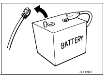
- When using air or electric power tools or hammers, always switch the Ignition OFF, disconnect the battery and wait at least three minutes before performing any service.
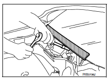
Precaution for Procedure without Cowl Top Cover
When performing the procedure after removing cowl top cover, cover the lower end of windshield with urethane, etc to prevent damage to windshield.
Liquid Gasket
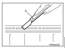
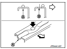
REMOVAL OF LIQUID GASKET SEALING
- After removing the bolts and nuts, separate the mating surface and remove the liquid gasket using Tool (A).
Tool Number (A): KV10111100 (J-37228)
CAUTION:
Be careful not to damage the mating surfaces.
- In areas where the cutter is difficult to use, use a plastic hammer to lightly tap (1) the cutter where the liquid gasket is applied. Use a plastic hammer to slide (2) the cutter by tapping on the side.
CAUTION:
Do not damage the mating surfaces.
LIQUID GASKET APPLICATION PROCEDURE
- Using suitable tool (A), remove old liquid gasket adhering to the liquid gasket application surface and the mating surface.
- Remove liquid gasket completely from the groove of the liquid gasket application surface, mounting bolts, and bolt holes.
- Wipe the liquid gasket application surface and the mating surface with white gasoline (lighting and heating use) to remove adhering moisture, grease and foreign materials.
- Attach liquid gasket tube using suitable tool.
Use Genuine Liquid Gasket or equivalent.
- Apply liquid gasket without gaps to the specified location according to the specified dimensions.
- If there is a groove for liquid gasket application, apply liquid gasket to the groove.
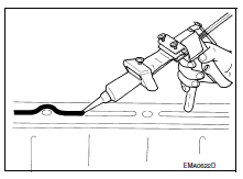
- As for bolt holes (B), normally apply liquid gasket inside the
holes. Occasionally, it should be applied outside the holes.
Check to read the text of this manual.
(A) : Groove
 : Inside
- Within five minutes of liquid gasket application, install the mating component.
- If liquid gasket protrudes, wipe it off immediately.
- Do not retighten mounting bolts or nuts after the installation.
- After 30 minutes or more have passed from the installation, fill engine oil and engine coolant.
CAUTION:
If there are specific instructions in this manual, observe them.
Precaution for TCM and Transaxle Assembly Replacement
CAUTION:
- To replace TCM, refer to TM-142, "Description".
- To replace transaxle assembly, refer to TM-144, "Description".
Precaution for G Sensor Removal/Installation or Replacement
CAUTION:
To remove/install or replace G sensor, refer to TM-147, "Description".
General Precautions
- Turn ignition switch OFF and disconnect the battery cable from the negative terminal before connecting or disconnecting the CVT assembly harness connector. Because battery voltage is applied to TCM even if ignition switch is turned OFF.
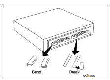
- When connecting or disconnecting pin connectors into or
from TCM, do not damage pin terminals (bend or break).
Check that there are not any bends or breaks on TCM pin terminal, when connecting pin connectors.
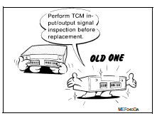
- Perform TCM input/output signal inspection and check
whether TCM functions normally or not before replacing TCM.
Refer to TM-114, "Reference Value".
- Perform “DTC (Diagnostic Trouble Code) CONFIRMATION
PROCEDURE”.
If the repair is completed DTC should not be displayed in the “DTC CONFIRMATION PROCEDURE”.
- Always use the specified brand of CVT fluid. Refer to MA-11, "Fluids and Lubricants".
- Use lint-free paper not cloth rags during work.
- Dispose of the waste oil using the methods prescribed by law, ordinance, etc. after replacing the CVT fluid.
On Board Diagnosis (OBD) System of CVT and Engine
The ECM has an on board diagnostic system. It will light up the malfunction indicator lamp (MIL) to warn the driver of a malfunction causing emission deterioration.
CAUTION:
- Be sure to turn the ignition switch OFF and disconnect the battery cable from the negative terminal before any repair or inspection work. The open/short circuit of related switches, sensors, solenoid valves, etc. will cause the MIL to light up.
- Be sure to connect and lock the connectors securely after work. A loose (unlocked) connector will cause the MIL to light up due to an open circuit. (Be sure the connector is free from water, grease, dirt, bent terminals, etc.)
- Be sure to route and secure the harnesses properly after work. Interference of the harness with a bracket, etc. may cause the MIL to light up due to a short circuit.
- Be sure to connect rubber tubes properly after work. A misconnected or disconnected rubber tube may cause the MIL to light up due to a malfunction of the EGR system or fuel injection system, etc.
- Be sure to erase the unnecessary malfunction information (repairs completed) from the TCM and ECM before returning the vehicle to the customer.
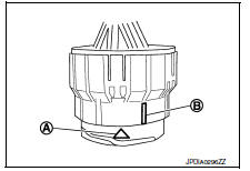
Removal and Installation Procedure for CVT Unit Connector
REMOVAL
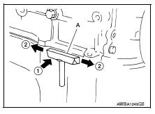
- Rotate bayonet ring (A) counterclockwise. Pull out CVT unit harness connector (B) upward and remove it.
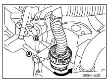
INSTALLATION
- Align marking (A) on CVT unit harness connector terminal with marking (B) on bayonet ring. Insert CVT unit harness connector.
- Rotate bayonet ring clockwise.
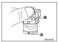
- Rotate bayonet ring clockwise until marking (A) on CVT unit harness connector terminal body is aligned with the slit (B) on bayonet ring as shown in the figure (correctly fitting condition).
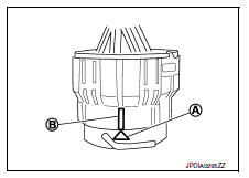
- Securely align marking (A) on CVT unit harness connector terminal body with bayonet ring slit (B). Then, be careful not to make a half fit condition as shown in the figure.
- Never mistake the slit of bayonet ring for other dent portion.
General Precautions
- Always use the specified brand of CVT fluid.
- Use lint-free paper not cloth rags during work.
- Dispose of the waste oil using the methods prescribed by law, ordinance, etc. after replacing the CVT fluid.
 CVT: RE0F11A
...
 Preparation
Special Service Tools
The actual shapes of Kent-Moore tools may differ from those of special
service tools illustrated here.
*: The O-ring as a unit part is set as a SST.
Commercial Service ...
Other materials:
ABS Warning lamp
Component Function Check
1.CHECK ABS WARNING LAMP FUNCTION
Check that ABS warning lamp in combination meter turns ON for
approximately 2 seconds after ignition switch
is turned ON.
Is the inspection result normal?
YES >> Inspection End.
NO >> Proceed to diagnosis procedure. ...
Head restraints/Headrests
WARNINGHead restraints/headrests supplement
the other vehicle safety systems. They may
provide additional protection against injury
in certain rear end collisions. Adjustable
head restraints/headrests must be
adjusted properly, as specified in this section.
Check the adjus ...
Waxing
Regular waxing protects the paint surface and
helps retain new vehicle appearance. Polishing is
recommended to remove built-up wax residue
and to avoid a weathered appearance before
re-applying wax.
A NISSAN dealer can assist you in choosing the
proper product.
Wax your vehicle only afte ...
