Nissan Sentra B18 (2020-2025) Service Manual: P219a Air Fuel Ratio
Dtc Description
DTC Description
DTC DETECTION LOGIC
|
DTC |
CONSULT screen terms (Trouble diagnosis content) |
DTC detection condition |
||
|
P219A |
00 |
AIR FUEL RATIO IMBALANCE B1 (Bank 1 air-fuel ratio imbalance) |
Diagnosis condition |
Engine running at idle |
|
Signal (terminal) |
— |
|||
|
Threshold |
ECM detects a lean/rich air fuel ratio state in any cylinder for a specified length of time |
|||
|
Diagnosis delay time |
— |
|||
POSSIBLE CAUSE
-
Direct fuel injector
-
Exhaust gas leaks
-
Incorrect fuel pressure
-
Mass air flow sensor
-
Intake air leaks
-
Lack of fuel
-
Incorrect PCV hose connection
-
Improper spark plug
-
Insufficient compression
-
The direct fuel injector circuit is open or shorted
-
ignition coil
-
The ignition signal circuit is open or shorted
FAIL-SAFE
Not applicable
Confirmation Procedure
Confirmation Procedure
-
CHECK DTC PRIORITY
If DTC P219A is displayed with other DTC, first perform the trouble diagnosis for the other DTC.
Is applicable DTC detected?
YES >>Perform diagnosis of applicable. Refer to DTC Index.
NO >>GO TO 2.
-
PRECONDITIONING-1
If DTC Confirmation Procedure has been previously conducted, always perform the following before conducting the next test.
-
Turn ignition switch OFF and wait at least 10 seconds.
-
Turn ignition switch ON.
-
Turn ignition switch OFF and wait at least 10 seconds.

Before performing the following procedure, confirm that battery voltage is 11 V or more at idle.
>>GO TO 3.
-
-
PRECONDITIONING-2
-
Turn ignition switch ON.
-
Clear the mixture ratio self-learning value. Refer to Work Procedure.
Will CONSULT be used?
YES >>GO TO 4.
NO >>GO TO 7.
-
-
PERFORM DTC CONFIRMATION PROCEDURE-1
-
Turn ignition switch ON.
-
Select “COOLAN TEMP/S” in “DATA MONITOR” mode of “ENGINE” using CONSULT.
-
Start engine.
-
Make sure that “COOLAN TEMP/S” indicates more than 80°C (176°F).
GO TO 5.
-
-
PERFORM DTC CONFIRMATION PROCEDURE-2
 With CONSULT
-
Select “SYSTEM 1 DIAGNOSIS B B1” and “SYSTEM 1 DIAGNOSIS A B1” in “DATA MONITOR” mode of “ENGINE” using CONSULT.
-
Drive Nissan Sentra vehicle under the following conditions for at least 5 consecutive seconds.
CAUTION:
-
Always drive Nissan Sentra vehicle at a safe speed.
Note:ENG SPEED
1,000 – 1,250rpm
COOLAN TEMP/S
More than 80°C (176°F)
B/FUEL SCHDL
4 – 7 ms
Selector lever
D position
SYSTEM 1 DIAGNOSIS B B1
PRSENT
-
Drive the Nissan Sentra vehicle at approximately 88 km/h (55MPH) allows easy diagnosis.
-
Keep the accelerator pedal as possible during cruising.
-
-
Check “SYSTEM 1 DIAGNOSIS A B1” indication.
Is “CMPLT” displayed?
YES >>GO TO 6.
NO >>GO TO 3.
-
-
PERFORM DTC CONFIRMATION PROCEDURE-3
Check 1st trip DTC.
Is 1st trip DTC detected?
YES >>Refer to DTC Diagnosis Procedure.
NO >>INSPECTION END
-
PERFORM DTC CONFIRMATION PROCEDURE-4
 Without CONSULT
-
Start the engine and warm it up to normal operating temperature.
-
Drive Nissan Sentra vehicle under the following conditions for at least 5 consecutive seconds.
CAUTION:
-
Always drive Nissan Sentra vehicle at a safe speed.
Note:Engine speed
1,000 – 1,250 rpm
Calculated load value
26 – 35 %
Selector lever
D position
-
Drive the Nissan Sentra vehicle at approximately 88 km/h (55MPH) allows easy diagnosis.
-
Keep the accelerator pedal as possible during cruising.
-
-
Check 1st trip DTC.
Is 1st trip DTC detected?
YES >>Refer to DTC Diagnosis Procedure.
NO >>INSPECTION END
-
Dtc Diagnosis Procedure
DTC Diagnosis Procedure
-
CHECK DTC PRIORITY
If DTC P219A is displayed with other DTC, first perform the trouble diagnosis for the other DTC.
Is applicable DTC detected?
YES >>Perform diagnosis of applicable. Refer to DTC Index.
NO >>GO TO 2.
-
CHECK FOR INTAKE AIR LEAK
-
Stop engine and check the following for connection.
-
Air duct
-
Vacuum hoses
-
PCV hose
-
Intake air passage between air duct to intake manifold
-
-
Start engine and let it idle.
-
Listen for an intake air leak after the mass air flow sensor.
Is the inspection result normal?
YES >>GO TO 3.
NO >>Repair or replace error-detected parts.
-
-
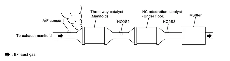
CHECK EXHAUST GAS LEAK
-
Stop engine and visually check exhaust tube, three way catalyst and muffler for dents connection.
-
Start engine and let it idle.
-
Listen for an exhaust gas leak before three way catalyst (manifold).
Is the inspection result normal?
YES >>GO TO 4.
NO >>Repair or replace error-detected parts.
-
-
CHECK FUEL PRESSURE
-
Release fuel pressure to zero. Refer to Work Procedure.
-
Check fuel pressure. Refer to Work Procedure.
Is the inspection result normal?
YES >>GO TO 5.
NO >>GO TO 9.
-
-
CHECK MASS AIR FLOW SENSOR
With CONSULTCheck “MASS AIR FLOW” in “DATA MONITOR” mode of “ENGINE” using CONSULT.
For specification, refer to MASS AIR FLOW SENSOR : Service Data.
 With GST
Check mass air flow sensor signal in Service $01 using GST.
For specification, refer to MASS AIR FLOW SENSOR : Service Data.
Is the inspection result normal?
YES >>GO TO 6.
NO >>Check connectors for rusted terminals or loose connections in the mass air flow sensor circuit or grounds. Refer to DTC Diagnosis Procedure.
-
CHECK FUNCTION OF FUEL INJECTOR-1
With CONSULT-
Start engine.
-
Perform “POWER BALANCE” in “ACTIVE TEST” mode of “ENGINE” using CONSULT.
-
Check that each circuit produces a momentary engine speed drop.
Without CONSULT-
Let engine idle.
-
Listen to each fuel injector operating sound.
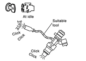
Clicking noise should be heard.
Is the inspection result normal?
YES >>GO TO 7.
NO >>Perform trouble diagnosis for fuel injector, refer to Component Function Check.
-
-
CHECK FUNCTION OF IGNITION COIL-1
CAUTION:
Perform the following steps in a well-ventilated area with no combustibles.
-
Turn ignition switch OFF.
-
Remove fuel pump fuse from IPDM E/R to release fuel pressure.
Note:
CONSULT must not be used to release fuel pressure. It develops again during the following steps, if released by using CONSULT.
-
Start the engine.
-
After an engine stall, crank the engine two or three times to release all the fuel pressure.
-
Turn ignition switch OFF.
-
Disconnect all the harness connectors of ignition coil to prevent electric discharge from occurring in ignition coil.
-
Remove ignition coil assembly and spark plug of cylinder. Refer to Removal and Installation.
-
Crank engine for 5 seconds or more to remove combustion gas in the cylinder.
-
Connect spark plug and harness connector to ignition coil.
-
Allow a 13-17mm (0.52-0.66 in) spacing between spark plug and grounded metal portion as shown in the figure to fix the ignition coil with a rope or an equivalent.
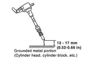
-
Crank the engine for approximately 3 seconds to see if sparking occurs between spark plug and the grounded metal portion.
Spark should be generated.
CAUTION:
-
The discharge voltage becomes 20 kV or higher. Therefore, always stay away from the spark plug and ignition coil at least 50 cm (19.7 in) during the inspection.
-
Leaving a space of more than 17mm (0.66 in) may damage the ignition coil.
When the gap is less than 13 mm (0.52 in), a the spark might be generated even if the coil is malfunctioning.
-
Is the inspection result normal?
YES >>GO TO 8.
NO >>GO TO 10.
-
-
CHECK COMPRESSION PRESSURE
Check compression pressure. Refer to Inspection.
Is the inspection result normal?
YES >>Check intermittent incident. Refer to Intermittent Incident.
NO >>Check pistons, piston rings, valves, valve seats and cylinder head gaskets.
-
DETECT MALFUNCTIONING PART
Check fuel hoses and fuel tubes for clogging.
Is the inspection result normal?
YES >>Replace fuel filter and fuel pump assembly. Refer to Removal and Installation.
NO >>Repair or replace error-detected parts.
-
CHECK FUNCTION OF IGNITION COIL-2
-
Turn ignition switch OFF.
-
Disconnect spark plug and connect a non-malfunctioning spark plug.
-
Crank engine for approximately 3 seconds, and recheck whether spark is generated between the spark plug and the grounded metal portion.
Spark should be generated.
Is the inspection result normal?
YES >>GO TO 11.
NO >>Check ignition coil, power transistor and their circuits. Refer to Component Function Check.
-
-
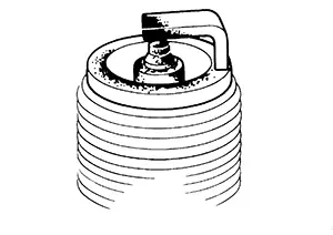
CHECK SPARK PLUG
Check the initial spark plug for fouling, etc.
Is the inspection result normal?
YES >>-
Repair or clean spark plug. Refer to Removal and Installation.
-
GO TO 12.
Replace spark plug(s) with standard type one(s). For spark plug type, refer to Spark Plug.
-
-
CHECK FUNCTION OF IGNITION COIL-3
-
Reconnect the initial spark plugs.
-
Crank engine for approximately 3 seconds, and recheck whether spark is generated between the spark plug and the grounded portion.
Spark should be generated.
Is the inspection result normal?
YES >>Check intermittent incident. Refer to Intermittent Incident.
NO >>Replace spark plug(s) with standard type one(s). For spark plug type, refer to Spark Plug.
-
Other materials:
U1040 Eng Comm Circuit
Dtc Description
DTC Description
DTC DETECTION LOGIC
DTC
CONSULT screen terms
(Trouble diagnosis
content)
DTC detection
condition
...
High Pressure Fuel Pump
Component Function Check
Component Function Check
CHECK HIGH PRESSURE FUEL PUMP
FUNCTION
With CONSULT
Start engine.
Select “FUEL PRES SEN V”
in “DATA MONITOR” mode of
“ENGINE” usi ...
P01f0 Engine Coolant Temperature
Dtc Description
DTC Description
DTC DETECTION LOGIC
DTC
CONSULT screen terms
(Trouble diagnosis
content)
DTC detection
condition
...