Nissan Sentra Service Manual: P2122, P2123 APP Sensor
DTC Logic
DTC DETECTION LOGIC
NOTE:
If DTC P2122 or P2123 is displayed with DTC P0643, first perform the trouble diagnosis for DTC P0643.
Refer to EC-353, "DTC Logic".
| DTC No. | CONSULT screen terms (Trouble diagnosis content) | DTC detecting condition | Possible cause |
| P2122 | APP SEN 1/CIRC (Throttle/Pedal position sensor/switch “D” circuit low) | An excessively low voltage from the APP sensor 1 is sent to ECM. |
|
| P2123 | APP SEN 1/CIRC (Throttle/Pedal position sensor/switch “D” circuit high) | An excessively high voltage from the APP sensor 1 is sent to ECM. |
DTC CONFIRMATION PROCEDURE
1.PRECONDITIONING
If DTC Confirmation Procedure has been previously conducted, always perform the following procedure before conducting the next test.
- Turn ignition switch OFF and wait at least 10 seconds
- Turn ignition switch ON
- Turn ignition switch OFF and wait at least 10 seconds.
TESTING CONDITION:
Before performing the following procedure, confirm that battery voltage is more than 8 V at idle.
>> GO TO 2.
2.PERFORM DTC CONFIRMATION PROCEDURE
- Start engine and let it idle for 1 second.
- Check DTC.
Is DTC detected? YES >> Proceed to EC-432, "Diagnosis Procedure".
NO >> INSPECTION END
Diagnosis Procedure
1.CHECK APP SENSOR 1 POWER SUPPLY
- Turn ignition switch OFF.
- Disconnect accelerator pedal position (APP) sensor harness connector.
- Turn ignition switch ON.
- Check the voltage between APP sensor harness connector and ground.
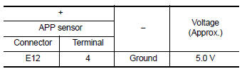
Is the inspection result normal? YES >> GO TO 3.
NO >> GO TO 2.
2.CHECK APP SENSOR 1 POWER SUPPLY CIRCUIT
- Turn ignition switch OFF.
- Disconnect ECM harness connector.
- Check the continuity between APP sensor harness connector and ECM harness connector.
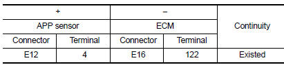
- Also check harness for short to ground.
Is the inspection result normal? YES >> Perform the trouble diagnosis for power supply circuit.
NO >> Repair or replace error-detected parts.
3.CHECK APP SENSOR 1 GROUND CIRCUIT
- Turn ignition switch OFF.
- Disconnect ECM harness connector.
- Check the continuity between APP sensor harness connector and ECM harness connector.
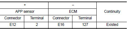
- Also check harness for short to power.
Is the inspection result normal? YES >> GO TO 4.
NO >> Repair or replace error-detected parts.
4.CHECK APP SENSOR 1 INPUT SIGNAL CIRCUIT
- Check the continuity between APP sensor harness connector and ECM harness connector
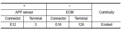
- Also check harness for short to ground and to power.
Is the inspection result normal? YES >> GO TO 5.
NO >> Repair or replace error-detected parts.
5.CHECK APP SENSOR
Check APP sensor. Refer to EC-433, "Component Inspection (APP Sensor)".
Is the inspection result normal? YES >> Check intermittent incident. Refer to GI-39, "Intermittent Incident".
NO >> Replace accelerator pedal assembly. Refer to ACC-3, "Removal and Installation".
Component Inspection (APP Sensor)
1.CHECK ACCELERATOR PEDAL POSITION SENSOR
- Turn ignition switch OFF.
- Reconnect all harness connectors disconnected.
- Turn ignition switch ON.
- Check the voltage between ECM harness connector terminals as per the following condition.
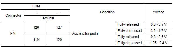
Is the inspection result normal? YES >> INSPECTION END
NO >> Replace accelerator pedal assembly. Refer to ACC-3, "Removal and Installation".
 P2119 Electric throttle control actuator
DTC Logic
DTC DETECTION LOGIC
DTC No.
CONSULT screen terms
(Trouble diagnosis content)
DTC detecting condition
Possible cause
P2119
ETC ACTR-B1
(Throttle actuator c ...
 P2127, P2128 APP Sensor
DTC Logic
DTC DETECTION LOGIC
DTC No.
CONSULT screen terms
(Trouble diagnosis content)
DTC detecting condition
Possible cause
P2127
APP SEN 2/CIRC
(Throttle/Pedal p ...
Other materials:
Precaution
Precaution for supplemental restraint system (srs) "air bag" and "seat
belt pre-tensioner"
The supplemental restraint system such as “air bag” and “seat belt pre-tensioner”,
used along
with a front seat belt, helps to reduce the risk or severity of injur ...
Engine Oils
Prolonged and repeated contact with used engine oil may cause skin cancer.
Try to avoid direct skin contact
with used oil.
If skin contact is made, wash thoroughly with soap or hand cleaner as soon as
possible.
HEALTH PROTECTION PRECAUTIONS
Avoid prolonged and repeated contact with oils ...
Engine maintenance
Drive belt
Drive belt : inspection
Alternator
Drive belt auto-tensioner
Crankshaft pulley
A/c compressor
Water pump
Drive belt
Possible use range
New drive belt range
Ndicator
Warning:
Perform this step when engine is stopped.
Check that the indicator of drive bel ...
