Nissan Sentra Service Manual: P099C Shift solenoid G
DTC Logic
| DTC | CONSULT screen terms (Trouble diagnosis content) | DTC detection condition | Possible causes |
| P099C | SHIFT SOLENOID G (Shift Solenoid G Control Circuit High) | The TCM high clutch & reverse brake solenoid
valve current monitor reading is 200 mA or
less continuously for 200 msec or more under
the following diagnosis conditions: Diagnosis conditions
|
|
DTC CONFIRMATION PROCEDURE
1.PREPARATION BEFORE WORK
If another “DTC CONFIRMATION PROCEDURE” occurs just before, turn ignition switch OFF and wait for at least 10 seconds, then perform the next test.
>> GO TO 2.
2.CHECK DTC DETECTION
- Start the engine and wait for 5 seconds or more
- Check the first trip DTC.
Is “P099C” detected? YES >> Go to TM-216, "Diagnosis Procedure".
NO >> INSPECTION END
Diagnosis Procedure
1.CHECK CIRCUIT BETWEEN TCM AND CVT UNIT
- Turn ignition switch OFF.
- Disconnect TCM connector and CVT unit connector.
- Check continuity between TCM harness connector terminal and CVT unit harness connector terminal.
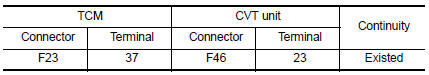
Is the inspection result normal? YES >> GO TO 2.
NO >> Repair or replace malfunctioning parts.
2.CHECK HIGH CLUTCH & REVERSE BRAKE SOLENOID VALVE
Check high clutch & reverse brake solenoid valve. Refer to TM-216, "Component Inspection".
Is the inspection result normal? YES >> Check intermittent incident. Refer to GI-39, "Intermittent Incident".
NO >> Repair or replace malfunctioning parts.
Component Inspection
1.CHECK HIGH CLUTCH & REVERSE BRAKE SOLENOID VALVE
Check resistance between CVT unit connector terminal and ground.
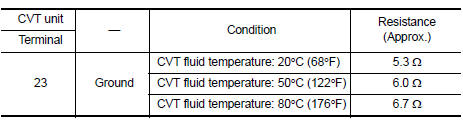
Is the inspection result normal? YES >> INSPECTION END
NO >> There is a malfunction of high & reverse brake solenoid valve. Replace transaxle assembly. Refer to TM-283, "Removal and Installation".
 P099B Shift solenoid G
DTC Logic
DTC DETECTION LOGIC
DTC
CONSULT screen terms
(Trouble diagnosis content)
DTC detection condition
Possible causes
P099B
SHIFT SOLENOID G
(Shift Solenoid G ...
 P1586 G Sensor
DTC Logic
DTC DETECTION LOGIC
DTC
CONSULT screen terms
(Trouble diagnosis content)
DTC detection condition
Possible causes
P1586
G Sensor
(Gravity Sensor Circuit)
...
Other materials:
Steering wheel turning force is heavy or light
Description
Steering wheel turning force is heavy or light.
Diagnosis Procedure
1.PERFORM SELF-DIAGNOSIS
With CONSULT
Turn the ignition switch OFF to ON.
Perform EPS self-diagnosis.
Is any DTC detected?
YES >> Check the DTC. Refer to STC-14, "DTC Index".
NO & ...
Unit disassembly and assembly
Moonroof unit assembly
Exploded view
Drain assembly
Glass lid
Weatherstrip
Moonroof rail assembly
Drain hose front (RH)
Moonroof motor assembly
Drain hose front (LH)
Side bracket (LH)
Drain hose rear (LH)
Sunshade stopper (LH)
Sunshade
Sunshade stopper (RH)
Drain hos ...
Starter motor drive control
STARTER MOTOR DRIVE CONTROL : System Description
SYSTEN DIAGRAM
*1: CVT models
*2: M/T models
INPUT/OUTPUT SIGNAL CHART
Sensor
Input signal to ECM
ECM function
Actuator
Crankshaft position sensor (POS)
Engine speed
Piston position
Starter ...
