Nissan Sentra Service Manual: P0500 VSS
EXCEPT FOR M/T MODELS
EXCEPT FOR M/T MODELS : Description
ECM receives vehicle speed signals from two different paths via CAN communication line: One is from the ABS actuator and electric unit (control unit) via the combination unit and the other is from TCM.
EXCEPT FOR M/T MODELS : DTC Logic
DTC DETECTION LOGIC
NOTE:
- If DTC P0500 is displayed with DTC UXXXX, first perform the trouble diagnosis for DTC UXXXX.
- If DTC P0500 is displayed with DTC P0607, first perform the trouble diagnosis for DTC P0607. Refer to EC- 350, "DTC Logic".
| DTC No. | CONSULT screen terms (Trouble diagnosis content) | DTC detecting condition | Possible cause |
| P0500 | VEHICLE SPEED SEN A (Vehicle speed sensor “A”) | At 20 km/h (13 MPH), ECM detects the following status continuously for 5 seconds or more: The difference between a vehicle speed calculated by a output speed sensor transmitted from TCM to ECM via CAN communication and the vehicle speed indicated on the combination meter exceeds 15km/h (10 MPH). |
|
DTC CONFIRMATION PROCEDURE
1.PRECONDITIONING
If DTC Confirmation Procedure has been previously conducted, always perform the following procedure before conducting the next test.
- Turn ignition switch OFF and wait at least 10 seconds.
- Turn ignition switch ON.
- Turn ignition switch OFF and wait at least 10 seconds.
>> GO TO 2.
2.PERFORM DTC CONFIRMATION PROCEDURE
- Start engine
- Shift the selector lever to D range and wait at least for 2 seconds.
- Drive the vehicle at least 10 seconds at 20 km/h (13 MPH) or more.
CAUTION:
Always drive vehicle at a safe speed.
NOTE:
This procedure may be conducted with the drive wheels lifted in the shop or by driving the vehicle. If a road test is expected to be easier, it is unnecessary to lift the vehicle.
- Check 1st trip DTC.
Is 1st trip DTC detected? YES >> Proceed to EC-330, "EXCEPT FOR M/T MODELS : Diagnosis Procedure" NO >> INSPECTION END
EXCEPT FOR M/T MODELS : Diagnosis Procedure
1.CHECK DTC WITH TCM
Check DTC with TCM. Refer to TM-108, "CONSULT Function".
Is the inspection result normal? YES >> GO TO 2.
NO >> Perform trouble shooting relevant to DTC indicated. Refer to TM-126, "DTC Index".
2.CHECK DTC WITH ABS ACTUATOR AND ELECTRIC UNIT (CONTROL UNIT)
Check DTC with ABS actuator and electric unit (control unit). Refer to BRC-31, "CONSULT Function (ABS)".
Is the inspection result normal? YES >> GO TO 3.
NO >> Perform trouble shooting relevant to DTC indicated. Refer to BRC-43, "DTC Index".
3.CHECK DTC WITH COMBINATION METER
Check DTC with combination meter. Refer to MWI-17, "CONSULT Function (METER/M&A)".
Is the inspection result normal? YES >> GO TO 4.
NO >> Perform trouble shooting relevant to DTC indicated. Refer to MWI-26, "DTC Index".
4.CHECK OUTPUT SPEED SENSOR
Check output speed sensor. Refer to TM-178, "Diagnosis Procedure".
Is the inspection result normal? YES >> GO TO 5.
NO >> Replace or replace error-detected parts.
5.CHECK WHEEL SENSOR
Check wheel sensor. Refer to BRC-68, "Diagnosis Procedure".
Is the inspection result normal? YES >> Check intermittent incident. Refer to GI-39, "Intermittent Incident".
NO >> Replace or replace error-detected parts.
M/T MODELS
M/T MODELS : Description
The vehicle speed signal is sent to the combination meter from the “ABS actuator and electric unit (control unit)” via the CAN communication line. The combination meter then sends a signal to the ECM via the CAN communication line.
M/T MODELS : DTC Logic
DTC DETECTION LOGIC
NOTE:
- If DTC P0500 is displayed with DTC UXXXX, first perform the trouble diagnosis for DTC UXXXX.
- If DTC P0500 is displayed with DTC P0607, first perform the trouble diagnosis for DTC P0607. Refer to EC-350, "DTC Logic".
| DTC No. | CONSULT screen terms (Trouble diagnosis content) | DTC detecting condition | Possible cause |
| P0500 | VEHICLE SPEED SEN A (Vehicle speed sensor “A”) | The vehicle speed signal sent to ECM is almost 0 km/h (0 MPH) even when vehicle is being driven. |
|
DTC CONFIRMATION PROCEDURE
1.INSPECTION START
Do you have CONSULT? Do you have CONSULT?
YES >> GO TO 2.
NO >> GO TO 5.
2.PRECONDITIONING
If DTC Confirmation Procedure has been previously conducted, always perform the following procedure before conducting the next test.
- Turn ignition switch OFF and wait at least 10 seconds.
- Turn ignition switch ON.
- Turn ignition switch OFF and wait at least 10 seconds.
>> GO TO 3.
3.CHECK VEHICLE SPEED SIGNAL
NOTE:
This procedure may be conducted with the drive wheels lifted in the shop or by driving the vehicle. If a road test is expected to be easier, it is unnecessary to lift the vehicle.
 With CONSULT
- Start engine.
- Read “VHCL SPEED SE” in “DATA MONITOR” mode of “ENGINE” using CONSULT. The vehicle speed on CONSULT should exceed 10 km/h (6 mph) when rotating wheels with suitable gear position.
Is the inspection result normal? YES >> GO TO 4.
NO >> Proceed to EC-333, "M/T MODELS : Diagnosis Procedure".
4.PERFORM DTC CONFIRMATION PROCEDURE
- Select “DATA MONITOR” mode of “ENGINE” using CONSULT.
- Warm engine up to normal operating temperature.
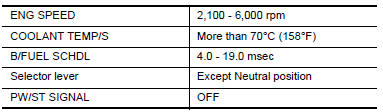
- Maintain the following conditions for at least 50 consecutive seconds.
CAUTION:
Always drive vehicle at a safe speed.
- Check 1st trip DTC.
Is 1st trip DTC detected? YES >> Proceed to EC-333, "M/T MODELS : Diagnosis Procedure".
NO >> INSPECTION END
5.PERFORM COMPONENT FUNCTION CHECK
Perform component function check. Refer to EC-332, "M/T MODELS : Component Function Check".
Use component function check to check the overall function of the vehicle speed signal circuit. During this check, a 1st trip DTC might not be confirmed.
Is the inspection result normal? YES >> INSPECTION END
NO >> Proceed to EC-333, "M/T MODELS : Diagnosis Procedure".
M/T MODELS : Component Function Check
1.PERFORM COMPONENT FUNCTION CHECK
 With GST
- Lift up drive wheels.
- Start engine.
- Read vehicle speed signal in Service $01 with GST.
The vehicle speed signal on GST should be able to exceed 10 km/h (6 MPH) when rotating wheels with suitable gear position.
Is the inspection result normal?
YES >> INSPECTION END
NO >> Proceed to EC-333, "M/T MODELS : Diagnosis Procedure".
M/T MODELS : Diagnosis Procedure
1.CHECK DTC WITH ABS ACTUATOR AND ELECTRIC UNIT (CONTROL UNIT)
Check DTC with ABS actuator and electric unit (control unit). Refer to BRC-31, "CONSULT Function (ABS)".
Is the inspection result normal? YES >> GO TO 2.
NO >> Perform trouble shooting relevant to DTC indicated. Refer to BRC-43, "DTC Index".
2.CHECK DTC WITH COMBINATION METER
Check DTC with combination meter. Refer to MWI-17, "CONSULT Function (METER/M&A)".
Is the inspection result normal? YES >> INSPECTION END
NO >> Perform trouble shooting relevant to DTC indicated. Refer to MWI-26, "DTC Index".
 P0462, P0463 Fuel level sensor
DTC Logic
DTC DETECTION LOGIC
NOTE:
If DTC P0462 or P0463 is displayed with DTC UXXXX, first perform the
trouble diagnosis for DTC
UXXXX.
If DTC P0462 or P0463 is displayed with DTC P0607 ...
 P0506 ISC System
Description
The ECM controls the engine idle speed to a specified level through the fine
adjustment of the air, which is let
into the intake manifold, by operating the electric throttle control ac ...
Other materials:
Regulatory Information
FCC Regulatory information
CAUTION: To maintain compliance with
FCC’s RF exposure guidelines, use only the
supplied antenna. Unauthorized antenna,
modification, or attachments could damage
the transmitter and may violate FCC regulations.
Operation is subject to the following two cond ...
Audio operation precautions
Compact disc (CD) player
CAUTION
Do not force a compact disc into the CD
insert slot. This could damage the CD
and/or CD player.
Trying to load a CD with the CD door
closed could damage the CD and/or CD
player.
Only one CD can be loaded into the CD
player at a time.
Only ...
OIL PAN
Exploded View
Transaxle assembly
Oil pan gasket
Magnet
Oil pan
Overflow tube
Drain plug gasket
Drain plug
Oil pan fitting bolt
: Always replace after every
disassembly.
: NВ·m (kg-m, ft-lb)
: NВ·m (kg-m, it-lb)
Removal and Installation
REMOVAL
Remove the en ...
