Nissan Sentra B18 (2020-2025) Service Manual: P0340 Cmp Sensor
Dtc Description
DTC Description
DTC DETECTION LOGIC
|
DTC |
CONSULT screen terms (Trouble diagnosis content) |
DTC detection condition |
|
|
P0340 |
CMP SEN/CIRC-B1 (Camshaft position sensor ŌĆ£AŌĆØ circuit bank 1 or single sensor) |
Diagnosis condition |
Engine: Cranking or running (idle speed or more than 800 rpm) |
|
Signal (terminal) |
Camshaft position sensor signal |
||
|
Threshold |
|
||
|
Diagnosis delay time |
ŌĆö |
||
POSSIBLE CAUSE
-
Harness or connectors
-
The camshaft position sensor circuit is open or shorted.
-
Sensor power supply circuit 2 is shorted.
-
-
Intake camshaft position sensor
-
Exhaust camshaft position sensor
-
Camshaft (INT)
-
Camshaft (EXT)
-
Starter motor
-
Starting system circuit
-
Dead (Weak) battery
-
Sensor power supply circuit 2 sensor
FAIL-SAFE
Engine Control System
|
Engine operating condition in fail-safe mode |
||
|---|---|---|
|
Fail safe mode |
Nissan Sentra Vehicle behavior |
|
|
Device fix mode |
|
|
|
Combustion control mode |
Stratified charge combustion control at starting |
No stratified charge combustion at starting (cold start). |
|
Idle speed control |
Stops feedback control of idle speed and controls with specified speed. |
|
|
Recovery speed control at decelerating |
Stops recovery speed control by the fuel cut at decelerating and controls with specified speed. |
|
|
Idle neutral control |
Stops idle neutral control. |
|
Idle Start/Stop System
When a DTC is detected, the start/stop indicator lamp blinks slowly and the idle start/stop system operation is prohibited.
When ECM detects error while operating the idle start/stop system, ECM restarts the engine.
Confirmation Procedure
Confirmation Procedure
-
PRECONDITIONING
If DTC Confirmation Procedure has been previously conducted, always turn ignition switch OFF and wait at least 10 seconds before conducting the next test.
TESTING CONDITION:
Before performing the following procedure, confirm that battery voltage is more than 10.5 V at idle.
>>GO TO 2.
-
DTC CONFIRMATION PROCEDURE-1
-
Start the engine and let it idle for at least 5 seconds.
If engine does not start, crank engine for at least 2 seconds.
-
Check 1st trip DTC.
Is 1st trip DTC detected?
YES >>Proceed to DTC Diagnosis Procedure.
NO >>GO TO 3.
-
-
DTC CONFIRMATION PROCEDURE-2
-
Maintaining engine speed at more than 800 rpm for at least 5 seconds.
-
Check 1st trip DTC.
Is 1st trip DTC detected?
YES >>Proceed to DTC Diagnosis Procedure.
NO-1 >>To check malfunction symptom before repair: Refer to Intermittent Incident.
NO-2 >>Confirmation after repair: INSPECTION END
-
Dtc Diagnosis Procedure
DTC Diagnosis Procedure
-
CHECK STARTING SYSTEM
Turn ignition switch to START position.
Does the engine turn over? Does the starter motor operate?
YES >>GO TO 2.
NO >>Check starting system. Refer to Work Flow (With 165-DSS-5000P) or Work Flow (Without 165-DSS-5000P).
-
CHECK CMP SENSOR (PHASE) POWER SUPPLY-1
-
Turn ignition switch OFF.
-
Disconnect camshaft position (CMP) sensor (PHASE) harness connector.
-
Turn ignition switch ON.
-
Check the voltage between CMP sensor (PHASE) harness connector terminals.
CMP sensor (PHASE)
Voltage
(Approx.)
Connector
+
ŌłÆ
Terminal
F39
1
2
5 V
Is the inspection result normal?
YES >>GO TO 8.
NO >>GO TO 3.
-
-
CHECK CMP SENSOR (PHASE) POWER SUPPLY-2
Check the voltage between CMP sensor (PHASE) harness connector and ground.
+
ŌłÆ
Voltage
(Approx.)
CMP sensor (PHASE)
Connector
Terminal
F39
1
Ground
5 V
Is the inspection result normal?
YES >>GO TO 6.
NO >>GO TO 4.
-
CHECK CMP SENSOR (PHASE) POWER SUPPLY CIRCUIT
-
Turn ignition switch OFF.
-
Disconnect ECM harness connector.
-
Check the continuity between CMP sensor (PHASE) harness connector and ECM harness connector.
CMP sensor (PHASE)
ECM
Continuity
Connector
Terminal
Connector
Terminal
F39
1
F24
24
Existed
Is the inspection result normal?
YES >>GO TO 5.
NO >>Repair or replace malfunctioning part.
-
-
CHECK SENSOR POWER SUPPLY 2 CIRCUIT
Refer to Diagnosis Procedure.
Is the inspection result normal?
YES >>Perform the trouble diagnosis for ECM power supply circuit. Refer to Diagnosis Procedure.
NO >>Replace malfunctioning part.
-
CHECK CMP SENSOR (PHASE) GROUND CIRCUIT
-
Turn ignition switch OFF.
-
Disconnect ECM harness connector.
-
Check the continuity between CMP sensor (PHASE) harness connector and ECM harness connector.
CMP sensor (PHASE)
ECM
Continuity
Connector
Terminal
Connector
Terminal
F39
2
F24
19
Existed
-
Also check harness for short to ground and short to power.
Is the inspection result normal?
YES >>GO TO 7.
NO >>Repair or replace malfunctioning part.
-
-
CHECK ECM GROUND CIRCUIT
-
Check the continuity between ECM harness connector and ground.
ECM
ŌĆö
Continuity
Connector
Terminal
F24
5
Ground
Existed
65
F25
69
E16
157
159
162
-
Also check harness for short to power.
Is the inspection result normal?
YES >>INSPECTION END
NO >>Repair or replace malfunctioning part.
-
-
CHECK CMP SENSOR (PHASE) INPUT SIGNAL CIRCUIT
-
Check the continuity between CMP sensor (PHASE) harness connector and ECM harness connector.
CMP sensor (PHASE)
ECM
Continuity
Connector
Terminal
Connector
Terminal
F39
3
F24
20
Existed
-
Also check harness for short to ground and short to power.
Is the inspection result normal?
YES >>GO TO 9.
NO >>Repair or replace malfunctioning part.
-
-
CHECK CAMSHAFT POSITION SENSOR (PHASE)
Refer to Component Inspection.
Is the inspection result normal?
YES >>GO TO 10.
NO >>Replace camshaft position sensor (PHASE). Refer to Exploded View.
-
CHECK CAMSHAFT (INT)
Check the following.
-
Accumulation of debris to the signal plate of camshaft
 rear end
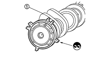
-
Chipping signal plate of camshaft rear end
Is the inspection result normal?
YES >>INSPECTION END
NO >>Remove debris and clean the signal plate of camshaft rear end or replace camshaft. Refer to Exploded View.
-
Other materials:
Side Radar Right (side Radar Rh)
C1e80-44 Control Unit
Dtc Description
DTC Description
DTC DETECTION LOGIC
DTC No.
CONSULT screen terms
(Trouble diagnosis
content)
DTC detecti ...
Camera Aiming Adjustment
Work Procedure
Work Procedure
Always adjust the camera aiming after removing and
installing or replacing the front camera unit.
Always adjust the camera aiming after removing and
installing or replacing the windshield glass.
CAUTION:
...
A/c Switch Assembly Signal Circuit
Diagnosis Procedure
Diagnosis Procedure
CHECK WITH SELF DIAGNOSTIC RESULT FUNCTION
CONSULT
Select ŌĆ£Self Diagnostic ResultŌĆØ mode of ŌĆ£HVACŌĆØ.
Check DTC.
...