Nissan Sentra B18 (2020-2025) Service Manual: P0335 Ckp Sensor
Dtc Description
DTC Description
DTC DETECTION LOGIC
|
DTC |
CONSULT screen terms (Trouble diagnosis content) |
DTC detection condition |
|
|
P0335 |
CKP SEN/CIRCUIT (Crankshaft position sensor ŌĆ£AŌĆØ circuit) |
Diagnosis condition |
Engine running or cranking |
|
Signal (terminal) |
Crankshaft position sensor (POS) signal |
||
|
Threshold |
|
||
|
Diagnosis delay time |
ŌĆö |
||
POSSIBLE CAUSE
-
Harness or connectors [Crankshaft position sensor (POS) circuit is open or shorted.]
-
Crankshaft position sensor (POS)
-
Signal plate
FAIL-SAFE
Engine Control System
|
Engine operating condition in fail-safe mode |
||
|---|---|---|
|
Fail safe mode |
Nissan Sentra Vehicle behavior |
|
|
Device fix mode |
|
|
|
Combustion control mode |
Stratified charge combustion control at starting |
No stratified charge combustion at starting (cold start). |
|
Idle speed control |
Stops feedback control of idle speed and controls with specified speed. |
|
|
Recovery speed control at decelerating |
Stops recovery speed control by the fuel cut at decelerating and controls with specified speed. |
|
|
Idle neutral control |
Stops idle neutral control. |
|
Idle Start/Stop System
When a DTC is detected, the start/stop indicator lamp blinks slowly and the idle start/stop system operation is prohibited.
When ECM detects error while operating the idle start/stop system, ECM restarts the engine.
Confirmation Procedure
Confirmation Procedure
-
CHECK DTC PRIORITY
If DTC P0335 is displayed with DTC P0643, first perform the trouble diagnosis for DTC P0643.
Is applicable DTC detected?
YES >>Perform diagnosis of applicable. Refer to DTC Description.
NO >>GO TO 2.
-
PRECONDITIONING
If DTC Confirmation Procedure has been previously conducted, always turn ignition switch OFF and wait at least 10 seconds before conducting the next test.
TESTING CONDITION:
Before performing the following procedure, confirm that battery voltage is more than 10.5 V at idle.
>>GO TO 3.
-
PERFORM DTC CONFIRMATION PROCEDURE
-
Start engine and let it idle for at least 5 seconds.
If engine does not start, crank engine for at least 2 seconds.
-
Check 1st trip DTC.
Is 1st trip DTC detected?
YES >>Proceed to DTC Diagnosis Procedure.
NO-1 >>To check malfunction symptom before repair: Refer to Intermittent Incident.
NO-2 >>Confirmation after repair: INSPECTION END
-
Dtc Diagnosis Procedure
DTC Diagnosis Procedure
-
CHECK DTC PRIORITY
If DTC P0335 is displayed with DTC P0643, first perform the trouble diagnosis for DTC P0643.
Is applicable DTC detected?
YES >>Perform diagnosis of applicable. Refer to DTC Description.
NO >>GO TO 2.
-
CHECK HARNESS CONNECTOR
-
Turn ignition switch OFF.
-
Disconnect crankshaft position (CKP) sensor harness connectors.
-
Reconnect crankshaft position (CKP) sensor harness connectors.
-
Perform DTC confirmation procedure
Is DTC detected?
YES >>GO TO 3.
NO >>INSPECTION END
-
-
CHECK GROUND CONNECTION
Check ground connection.
Is the in spection result normal?
YES >>GO TO 4.
NO >>Repair or replace ground connection.
-
CHECK CKP SENSOR (POS) POWER SUPPLY CIRCUIT-1
-
Turn ignition switch OFF.
-
Disconnect crankshaft position (CKP) sensor (POS) harness connector.
-
Turn ignition switch ON.
-
Check the voltage between CKP sensor (POS) harness connector and ground.
CKP sensor (POS)
Condition
Voltage
(Approx.)
Connector
+
ŌłÆ
Terminal
F22*1
F40*2
1
2
Ignition switch: ON
5 V
Ignition switch: OFF
0 V
*1: Without idle start/stop system
*2: With idle start/stop system
Is the inspection result normal?
YES >>GO TO 9.
NO >>GO TO 5.
-
-
CHECK CKP SENSOR (POS) POWER SUPPLY CIRCUIT-2
-
Turn ignition switch OFF.
-
Disconnect ECM harness connector.
-
Check the continuity between CKP sensor (POS) harness connector and ECM harness connector.
CKP sensor (POS)
ECM
Continuity
Connector
Terminal
Connector
Terminal
F22*1
F40*2
1
F24
16
Existed
*1: Without idle start/stop system
*2: With idle start/stop system
Is the inspection result normal?
YES >>GO TO 6.
NO >>Repair or replace malfunctioning part.
-
-
CHECK CKP SENSOR (POS) GROUND CIRCUIT
-
Turn ignition switch OFF.
-
Disconnect ECM harness connector.
-
Check the continuity between CKP sensor (POS) harness connector and ECM harness connector.
CKP sensor (POS)
ECM
Continuity
Connector
Terminal
Connector
Terminal
F22*1
F40*2
2
F24
17
Existed
*1: Without idle start/stop system
*2: With idle start/stop system
Is the inspection result normal?
YES >>GO TO 7.
NO >>Repair or replace malfunctioning part.
-
-
CHECK ECM GROUND CIRCUIT
-
Check the continuity between ECM harness connector and ground.
ECM
ŌĆö
Continuity
Connector
Terminal
F24
5
Ground
Existed
65
F25
69
E16
157
159
162
-
Also check harness for short to power.
Is the inspection result normal?
YES >>GO TO 8.
NO >>Repair or replace malfunctioning part.
-
-
CHECK CKP SENSOR (POS) POWER SUPPLY CIRCUIT-3
-
Turn ignition switch OFF.
-
Disconnect ECM harness connector.
-
Check the continuity between CKP sensor (POS) harness connector and ECM harness connector.
CKP sensor (POS)
ECM
Continuity
Connector
Terminal
Connector
Terminal
F22*1
F40*2
3
F24
21
Existed
*1: Without idle start/stop system
*2: With idle start/stop system
Is the inspection result normal?
YES >>GO TO 9.
NO >>Repair or replace malfunctioning part.
-
-
CHECK CKP SENSOR (POS)
Refer to Component Inspection.
Is the inspection result normal?
YES >>GO TO 10.
NO >>Replace crankshaft position sensor (POS). Refer to Exploded View.
-
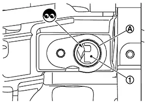
CHECK GEAR TOOTH
-
Remove crankshaft position sensor (POS). Refer to Exploded View.
-
Look into the mounting hole
 of the crankshaft position
sensor (POS) to check that there is no missing gear
tooth in the signal plate
of the crankshaft position
sensor (POS) to check that there is no missing gear
tooth in the signal plate  .
.
Is the inspection result normal?
YES >>INSPECTION END
NO >>Replace the signal plate. Refer to Exploded View.
-
Other materials:
Precaution. Precautions
Precautions
Precaution for Supplemental Restraint System (srs) "air Bag" and "seat Belt Pre-Tensioner"
Precaution for Supplemental Restraint System (SRS) "AIR BAG" and "SEAT BELT PRE-TENSIONER"
The Supplemental Restraint System such as
ŌĆ£AIR BAGŌĆØ and ŌĆ£SEAT BELT PRE-TENSIONERŌĆØ,
u ...
P0014 Evt Control
Dtc Description
DTC Description
DTC DETECTION LOGIC
DTC
CONSULT screen terms
(Trouble diagnosis
content)
DTC detection
condition
...
Handling Precaution
Precaution for Idle Start/stop System
Precaution for Idle Start/Stop System
PRECAUTIONS FOR IDLE START/STOP SYSTEM OPERATION
The operation of the idle start/stop system system needs to
satisfy various conditions. For details of the conditions, refer to System Description.
The idle start ...