Nissan Sentra B18 (2020-2025) Service Manual: P0300 Misfire
Dtc Description
DTC Description
When a misfire occurs, engine speed will fluctuate. If the engine speed fluctuates enough to cause the crankshaft position (CKP) sensor signal to vary, ECM can determine that a misfire is occurring.
|
Sensor |
Input signal to ECM |
ECM function |
|---|---|---|
|
Crankshaft position sensor |
Engine speed |
On board diagnosis of misfire |
The misfire detection logic consists of the following two conditions.
-
One Trip Detection Logic (Three Way Catalyst Damage)
On the 1st trip that a misfire condition occurs that can damage the three way catalyst (TWC) due to overheating, the MIL will blink.
When a misfire condition occurs, the ECM monitors the CKP sensor signal every 200 engine revolutions for a change.
When the misfire condition decreases to a level that will not damage the TWC, the MIL will turn off.
If another misfire condition occurs that can damage the TWC on a second trip, the MIL will blink.
When the misfire condition decreases to a level that will not damage the TWC, the MIL will remain on.If another misfire condition occurs that can damage the TWC, the MIL will begin to blink again.
-
Two Trip Detection Logic (Exhaust quality deterioration)
For misfire conditions that will not damage the TWC (but will affect Nissan Sentra vehicle emissions), the MIL will only light when the misfire is detected on a second trip. During this condition, the ECM monitors the CKP sensor signal every 1,000 engine revolutions.
DTC DETECTION LOGIC
|
DTC |
CONSULT screen terms (Trouble diagnosis content) |
DTC detection condition |
|
|
P0300 |
MULTI CYL MISFIRE (Random/Multiple cylinder misfire detected) |
Diagnosis condition |
ŌĆö |
|
Signal (terminal) |
ŌĆö |
||
|
Threshold |
Multiple cylinders misfire |
||
|
Diagnosis delay time |
ŌĆö |
||
POSSIBLE CAUSE
-
Improper spark plug
-
Insufficient compression
-
Incorrect fuel pressure
-
The fuel injector circuit is open or shorted.
-
Fuel injector
-
Intake air leakage
-
The ignition signal circuit is open or shorted.
-
Lack of fuel
-
Signal plate
-
A/F sensor 1
-
Mass air flow sensor
-
Incorrect PCV hose connection
FAIL-SAFE
Engine Control System
|
Engine operating condition in fail-safe mode |
||
|---|---|---|
|
Fail safe mode |
Nissan Sentra Vehicle behavior |
|
|
Traveling control mode |
Accelerator angle variation control |
ECM controls the accelerator pedal depression speed to make it slower than actual speed. This causes a drop in accelerating performance and encourages the driver to repair malfunction. Note:
ECM does not control the accelerator pedal releasing speed. |
|
Combustion control mode |
Stratified charge combustion control at starting |
No stratified charge combustion at starting (cold start). |
|
Idle speed control |
Stops feedback control of idle speed and controls with specified speed. |
|
|
Recovery speed control at decelerating |
Stops recovery speed control by the fuel cut at decelerating and controls with specified speed. |
|
|
Idle neutral control |
Stops idle neutral control. |
|
Idle Start/Stop System
When a DTC is detected, the start/stop indicator lamp blinks slowly and the idle start/stop system operation is prohibited.
When ECM detects error while operating the idle start/stop system, ECM restarts the engine.
Confirmation Procedure
Confirmation Procedure
-
PRECONDITIONING
If DTC Confirmation Procedure has been previously conducted, always turn ignition switch OFF and wait at least 10 seconds before conducting the next test.
Will CONSULT be used?
YES >>GO TO 2.
NO >>GO TO 4.
-
PERFORM DTC CONFIRMATION PROCEDURE-1
 With CONSULT
-
Start the engine and warm it up to normal operating temperature.
-
Turn ignition switch OFF and wait at least 10 seconds.
-
Restart engine and let it idle for about 35 minutes.
-
Check 1st trip DTC.
Is 1st trip DTC detected?
YES >>Proceed to DTC Diagnosis Procedure.
NO >>GO TO 3.
-
-
PERFORM DTC CONFIRMATION PROCEDURE-2
-
Turn ignition switch OFF and wait at least 10 seconds.
-
Start the engine and drive the Nissan Sentra vehicle under similar conditions to (1st trip) Freeze Frame Data for a certain time. Refer to the table below.
Hold the accelerator pedal as steady as possible.
Similar conditions to (1st trip) Freeze Frame Data mean that the following conditions should be satisfied at the same time.
Engine speed
Engine speed in the freeze frame data ┬▒ 400 rpm
Nissan Sentra Vehicle speed
Vehicle speed in the freeze frame data ┬▒ 10 km/h (6 MPH)
Base fuel schedule
Base fuel schedule in the freeze frame data ┬▒ 10%
Engine coolant temperature (T) condition
When the freeze frame data shows lower than 70┬░C (158┬░F), T should be lower than 70┬░C (158┬░F).
When the freeze frame data shows higher than or equal to 70┬░C (158┬░F), T should be higher than or equal to 70┬░C (158┬░F).
Driving time varies according to the engine speed in the freeze frame data.
Engine speed
Time
Around 1,000 rpm
Approximately 10 minutes
Around 2,000 rpm
Approximately 5 minutes
More than 3,000 rpm
Approximately 3.5 minutes
-
Check 1st trip DTC.
Is 1st trip DTC detected?
YES >>Proceed to DTC Diagnosis Procedure.
NO-1 >>To check malfunction symptom before repair: Refer to Intermittent Incident.
NO-2 >>Confirmation after repair: INSPECTION END
-
-
PERFORM DTC CONFIRMATION PROCEDURE-3
 Without CONSULT
-
Start engine and warm it up to normal operating temperature.
-
Turn ignition switch OFF and wait at least 10 seconds.
-
Restart engine and let it idle for about 35 minutes.
-
Check 1st trip DTC.
Is 1st trip DTC detected?
YES >>Proceed to DTC Diagnosis Procedure.
NO-1 >>To check malfunction symptom before repair: Refer to Intermittent Incident.
NO-2 >>Confirmation after repair: INSPECTION END
-
Dtc Diagnosis Procedure
DTC Diagnosis Procedure
-
CHECK GROUND CONNECTION
Check the following.
-
Connection condition of the ground E9 and E15
-
Connection condition of the ground harness between engine assembly and Nissan Sentra vehicle body (If equipped)
Is the inspection result normal?
YES >>GO TO 2.
NO >>Repair or replace error-detected parts.
-
-
CHECK FOR INTAKE AIR LEAKAGE AND PCV HOSE
-
Start the engine and run it at idle speed.
-
Listen for the sound of the intake air leakage.
-
Check PCV hose connection.
Is intake air leakage detected?
YES >>Discover air leakage location and repair. Refer to Exploded View.
NO >>GO TO 3.
-
-
CHECK FOR EXHAUST SYSTEM CLOGGING
Stop engine and visually check exhaust tube, three way catalyst and muffler for dents.
Is the inspection result normal?
YES-1 >>With CONSULT: GO TO 4.
YES-2 >>Without CONSULT: GO TO 5.
NO >>Repair or replace malfunctioning part. Refer to Exploded View.
-
PERFORM POWER BALANCE TEST
With CONSULT-
Start the engine.
-
Perform ŌĆ£POWER BALANCEŌĆØŌĆ£ACTIVE TESTŌĆØ mode of ŌĆ£ENGINEŌĆØ with CONSULT.
-
Check that each circuit produces a momentary engine speed drop.
Is the inspection result normal?
YES >>GO TO 10.
NO >>GO TO 5.
-
-
CHECK FUNCTION OF FUEL INJECTOR
Without CONSULT-
Start engine.
-
Listen to each fuel injector operation.
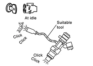
Clicking sound should be heard.
Is the inspection result normal?
YES >>GO TO 6.
NO >>Perform trouble diagnosis for fuel injector, Refer to Diagnosis Procedure.
-
-
CHECK FUNCTION OF IGNITION COIL-1
CAUTION:
Perform the following procedure in a place with no combustible objects and good ventilation.
-
Turn ignition switch OFF.
-
Remove fuel pump fuse in IPDM E/R to release fuel pressure.
Note:
Do not use CONSULT to release fuel pressure, or fuel pressure applies again during the following procedure.
-
Start engine.
-
After engine stalls, crank it 2 or 3 times to release all fuel pressure.
-
Turn ignition switch OFF.
-
Remove all ignition coil harness connectors to avoid the electrical discharge from the ignition coils.
-
Remove ignition coil and spark plug of the cylinder to be checked. Refer to Exploded View.
-
Crank engine for 5 seconds or more to remove combustion gas in the cylinder.
-
Connect spark plug and harness connector to ignition coil.
-
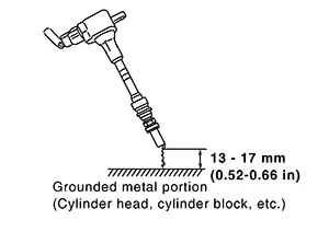
Fix ignition coil using a rope etc. with gap of 13 - 17 mm (0.52 - 0.66 in) between the edge of the spark plug and grounded metal portion as shown in the figure.
-
Crank engine for approximately 3 seconds, and check whether spark is generated between the spark plug and the grounded metal portion.
Spark should be generated.
CAUTION:
-
Never place the spark plug and the ignition coil within 50 cm (19.7 in) each other. Be careful not to get an electrical shock while checking, because the electrical discharge voltage becomes 20 kV or more.
-
It might damage the ignition coil if the gap of more than 17 mm (0.66 in) is made.
When the gap is less than 13 mm (0.52 in), a spark might be generated even if the coil is malfunctioning.
-
Is the inspection result normal?
YES >>GO TO 10.
NO >>GO TO 7.
-
-
CHECK FUNCTION OF IGNITION COIL-2
-
Turn ignition switch OFF.
-
Disconnect spark plug and connect a non-malfunctioning spark plug.
-
Crank engine for approximately 3 seconds, and recheck whether spark is generated between the spark plug and the grounded metal portion.
Spark should be generated.
Is the inspection result normal?
YES >>GO TO 8.
NO >>Check ignition coil, power transistor and their circuits. Refer to Diagnosis Procedure.
-
-
CHECK SPARK PLUG
Check the initial spark plug for fouling, etc.
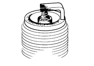
Is the inspection result normal?
YES >>Replace spark plug(s) with standard type one(s). Refer to Exploded View.
NO >>Repair or clean spark plug. Then GO TO 9.
-
CHECK FUNCTION OF IGNITION COIL-3
-
Reconnect the initial spark plugs.
-
Crank engine for approximately 3 seconds, and recheck whether spark is generated between the spark plug and the grounded portion.
Spark should be generated.
Is the inspection result normal?
YES >>INSPECTION END
NO >>Replace spark plug(s) with standard type one(s). Refer to Exploded View.
-
-
CHECK COMPRESSION PRESSURE
Check compression pressure. Refer to Inspection.
Is the inspection result normal?
YES >>GO TO 11.
NO >>Check pistons, piston rings, valves, valve seats and cylinder head gaskets.
-
CHECK FUEL PRESSURE
-
Install all removed parts.
-
Release fuel pressure. Refer to Work Procedure.
-
Set a fuel pressure meter and check fuel pressure. Refer to Work Procedure.
At idle: Approx. 3,000 kPa (30.0 bar, 30.6 kg/cm2, 435 psi)
Is the inspection result normal?
YES >>GO TO 13.
NO >>GO TO 12.
-
-
DETECT MALFUNCTIONING PART
Check fuel hoses and fuel tubes for clogging.
Is the inspection result normal?
YES >>Replace ŌĆ£fuel level sensor unit, fuel filter and fuel pump assemblyŌĆØ. Refer to Removal and Installation.
NO >>Repair or replace malfunctioning part.
-
CHECK IDLE SPEED AND IGNITION TIMING
Check idle speed and ignition timing.
Idle speed: For procedure, Refer to IDLE SPEED : Periodic Maintenance, for specification, Refer to IDLE SPEED : Periodic Maintenance, for specification, Refer to Service Data.
Ignition timing: For procedure, Refer to IGNITION TIMING : Periodic Maintenance, for specification, Refer to Service Data.
Is the inspection result normal?
YES >>GO TO 14.
NO >>Perform basic inspection. Refer to Work Procedure.
-
CHECK A/F SENSOR 1 INPUT SIGNAL CIRCUIT
-
Turn ignition switch OFF.
-
Disconnect corresponding A/F sensor 1 harness connector.
-
Disconnect ECM harness connector.
-
Check the continuity between A/F sensor 1 harness connector and ECM harness connector.
A/F sensor 1
ECM
Continuity
Connector
Terminal
Connector
Terminal
F12
1
F25
86
Existed
2
88
-
Check the continuity between A/F sensor 1 harness connector and ground, or ECM harness connector and ground.
A/F sensor 1
ŌĆö
Continuity
Connector
Terminal
F12
1
Ground
Not existed
2
ECM
ŌĆö
Continuity
Connector
Terminal
F25
86
Ground
Not existed
88
-
Also check harness for short to ground and short to power.
Is the inspection result normal?
YES >>GO TO 15.
NO >>Repair or replace malfunctioning part.
-
-
CHECK A/F SENSOR 1 HEATER
Refer to Component Inspection.
Is the inspection result normal?
YES >>GO TO 16.
NO >>Replace malfunctioning A/F sensor 1. Refer to Exploded View.
-
CHECK MASS AIR FLOW SENSOR OUTPUT VOLTAGE
With CONSULT-
Install all removed parts.
-
Start engine and warm it up to normal operating temperature.
-
Select ŌĆ£MASS AIR FLOW SENSOR (Hz)ŌĆØ in ŌĆ£DATA MONITORŌĆØ mode using CONSULT and check the indication under the following condition.
Monitor item
Condition
Indication
MASS AIR FLOW SENSOR (Hz)
Ignition switch ON (Engine stopped.)
Approx. 3,700 Hz
Idle (Engine is warmed-up to normal operating temperature.)
Approx. 5,500 Hz
Idle to about 4,000 rpm
5,500 Hz ŌåÆ 7,000 Hz*
*: Check for linear frequency rise in response to increase of engine speed.
Without CONSULT-
Install all removed parts.
-
Start engine and warm it up to normal operating temperature.
-
Check the frequency between ECM harness connector terminals under the following conditions.
ECM
Condition
Frequency
Connector
+
ŌłÆ
Terminal
F24
26
23
Ignition switch ON (Engine stopped.)
Approx. 3,700 Hz
Idle (Engine is warmed-up to normal operating temperature.)
Approx. 5,500 Hz
Idle to about 4,000 rpm
5,500 Hz ŌåÆ 7,000 Hz*
*: Check for linear frequency rise in response to increase of engine speed.
Is the inspection result normal?
YES >>GO TO 17.
NO >>Check connectors for rusted terminals or loose connections in the mass air flow sensor circuit or ground. Refer to DTC Diagnosis Procedure.
-
-
CHECK SYMPTOM MATRIX CHART
Check items on the rough idle symptom in Symptom Table.
Is the inspection result normal?
YES >>GO TO 18.
NO >>Repair or replace malfunctioning part.
-
ERASE THE 1ST TRIP DTC
Some tests may cause a 1st trip DTC to be set.
Erase the 1st trip DTC from the ECM memory after performing the tests. Refer to Diagnosis Description.
>>INSPECTION END
Other materials:
Knock Sensor
Component Inspection
Component Inspection
CHECK KNOCK SENSOR
Turn ignition switch OFF.
Disconnect knock sensor harness
connector.
Check resistance between knock sensor
terminals ...
Low Tire Pressure Warning Lamp Does Not Turn Off
Symptom Description
Symptom Description
The low tire pressure warning lamp does not turn
OFF after several seconds is passed after the engine starts.
Diagnosis Procedure
Diagnosis Procedure
CHECK TIRE PRESSURE
Ignition switch ...
Trunk Opener Request Switch
Component Function Check
Component Function Check
CHECK FUNCTION
CONSULT
Select "Request switch BD/TR" in "Data Monitor"
mode of "BCM(TRUNK)".
Select that the functi ...