Nissan Sentra Service Manual: P0196 EOT Sensor
DTC Logic
DTC DETECTION LOGIC
NOTE:
If DTC P0196 is displayed with DTC P0197 or P0198, first perform the trouble diagnosis for DTC P0197 or P0198. Refer to EC-264, "DTC Logic".
| DTC No. | CONSULT screen terms (Trouble diagnosis content) | DTC detecting condition | Possible cause | |
| P0196 | EOT SENSOR (Engine oil temperature sensor range/performance) | A) | Rationally incorrect voltage from the sensor is sent to ECM, compared with the voltage signals from EOT sensor and intake air temperature sensor. |
|
| B) | The comparison result of signals transmitted to ECM from each temperature sensor (IAT sensor, ECT sensor, FTT sensor, and EOT sensor) shows that the signal voltage of the EOT sensor is higher/ lower than that of other temperature sensors when the engine is started with its cold state. |
|
||
DTC CONFIRMATION PROCEDURE
1.INSPECTION START
Is it necessary to erase permanent DTC? YES >> GO TO 6.
NO >> GO TO 2.
2.PRECONDITIONING
If DTC CONFIRMATION PROCEDURE has been previously conducted, always perform the following procedure before conducting the next test.
- Turn ignition switch OFF and wait at least 10 seconds.
- Turn ignition switch ON.
- Turn ignition switch OFF and wait at least 10 seconds.
TESTING CONDITION:
Before performing the following procedure, confirm that battery voltage is 11 V or more at idle.
>> GO TO 3.
3.PERFORM DTC CONFIRMATION PROCEDURE FOR MALFUNCTION A-1
- Start engine and warm it up to normal operating temperature.
- Turn ignition switch OFF and wait at least 10 seconds.
- Turn ignition switch ON.
- Turn ignition switch OFF and wait at least 10 seconds.
- Start engine and let it idle for 5 minutes and 10 seconds.
- Check 1st trip DTC.
Is 1st trip DTC detected? YES >> Proceed to EC-263, "Diagnosis Procedure".
NO >> GO TO 4.
4.PERFORM DTC CONFIRMATION PROCEDURE FOR MALFUNCTION A-2
 With CONSULT
- Select “DATA MONITOR” mode of “ENGINE” using CONSULT.
- Check that “COOLANT TEMP/S” indicates above 80°C (176°F).
If it is above 80В°C (176В°F), go to the following steps.
If it is below 80°C (176°F), warm engine up until “COOLANT TEMP/S” indicates more than 80°C (176°F).
Then perform the following steps.
- Turn ignition switch OFF and soak the vehicle in a cool place.
- Turn ignition switch ON.
NOTE:
Do not turn ignition switch OFF until step 8.
- Select “DATA MONITOR” mode of “ENGINE” using CONSULT.
- Check the following.
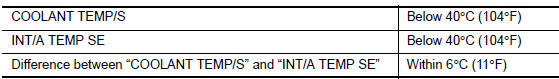
If they are within the specified range, perform the following steps.
If they are out of the specified range, soak the vehicle to meet the above conditions. Then perform the following steps.
NOTE:
- Do not turn ignition switch OFF.
- If it is supposed to need a long period of time, do not deplete the battery.
- Start engine and let it idle for 5 minutes.
- Check 1st trip DTC.
 With GST
Follow the procedure “With CONSULT” above.
Is 1st trip DTC detected? YES >> Proceed to EC-263, "Diagnosis Procedure".
NO >> GO TO 5.
5.PERFORM COMPONENT FUNCTION CHECK (FOR MALFUNCTION B)
Perform component function check. Refer to EC-263, "Component Function Check".
NOTE:
Use the component function check to check the overall function of the EOT sensor circuit. During this check, a 1st trip DTC might not be confirmed.
Is the inspection result normal? YES >> INSPECTION END
NO >> Proceed to EC-263, "Diagnosis Procedure".
6.PRECONDITIONING
If DTC CONFIRMATION PROCEDURE has been previously conducted, always perform the following procedure before conducting the next test.
- Turn ignition switch OFF and wait at least 10 seconds.
- Turn ignition switch ON.
- Turn ignition switch OFF and wait at least 10 seconds.
TESTING CONDITION:
- Before performing the following procedure, do not add fuel.
- Before performing the following procedure, check that fuel level is between 1/4 and 4/4.
- Before performing the following procedure, confirm that battery voltage is 11 V or more at idle.
>> GO TO 7.
7.PERFORM DTC CONFIRMATION PROCEDURE B
- Move the vehicle to a cool place.
NOTE:
Cool the vehicle in an environment of ambient air temperature between −10В°C (14В°F) and 35В°C (95В°F).
- Turn ignition switch OFF and leave the vehicle for 12 hours.
CAUTION:
Never turn ignition switch ON during this procedure.
NOTE:
The vehicle must be cooled with the food open.
- Start engine and let it idle for 5 minutes or more.
CAUTION:
Never turn ignition switch OFF during idling.
- Check 1st trip DTC.
Is 1st trip DTC detected? YES >> Proceed to EC-263, "Diagnosis Procedure".
NO >> INSPECTION END
Component Function Check
1.CHECK ENGINE OIL TEMPERATURE (EOT) SENSOR
- Turn ignition switch OFF.
- Disconnect EOT sensor harness connector.
- Remove EOT sensor. Refer to EM-94, "Exploded View".
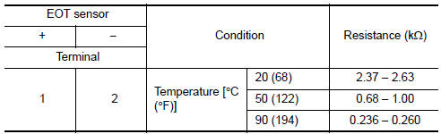
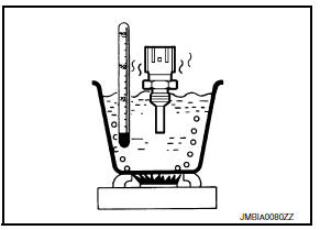
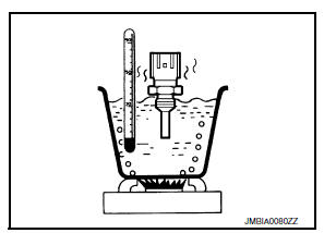
- Check resistance between EOT sensor terminals by heating with hot water as shown in the figure.
Is the inspection result normal? YES >> Check intermittent incident. Refer to GI-39, "Intermittent Incident".
NO >> Proceed to EC-263, "Diagnosis Procedure".
Diagnosis Procedure
1.CHECK ENGINE OIL TEMPERATURE (EOT) SENSOR
Check EOT sensor. Refer to EC-263, "Component Inspection".
Is the inspection result normal? YES >> Check intermittent incident. Refer to GI-39, "Intermittent Incident".
NO >> Replace EOT sensor. Refer to EM-94, "Exploded View".
Component Inspection
1.CHECK ENGINE OIL TEMPERATURE SENSOR
- Turn ignition switch OFF.
- Disconnect engine oil temperature sensor harness connector.
- Remove engine oil temperature sensor.
- Check resistance between engine oil temperature sensor terminals by heating with hot water as shown in the figure.
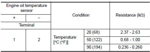
Is the inspection result normal? YES >> INSPECTION END
NO >> Replace engine oil temperature sensor. Refer to EM-94, "Exploded View".
 P0182, P0183 FTT Sensor
DTC Logic
DTC DETECTION LOGIC
DTC No.
CONSULT screen terms
(Trouble diagnosis content)
DTC detecting condition
Possible cause
P0182
FTT SEN/CIRCUIT
(Fuel temperatur ...
 P0197, P0198 EOTSensor
DTC Logic
DTC DETECTION LOGIC
DTC No.
CONSULT screen terms
(Trouble diagnosis content)
DTC detecting condition
Possible cause
P0197
EOT SEN/CIRC
(Engine oil tempera ...
Other materials:
Fuel gauge
NOTE:
The ignition switch must be placed in the
ON position for the gauge to give a reading.
The gauge indicates the approximate fuel level
in the tank.
The gauge may move slightly during braking,
turning, acceleration, or going up or down hills.
The low fuel warning light comes on when ...
Diagnosis description : malfunction indicator lamp (MIL)
When emission-related ECU detects a malfunction in the emission
control systems components and/or the powertrain control components
(which affect vehicle emissions), it turns on/blinks MIL to
inform the driver that a malfunction has been detected.
The MIL illuminates when ignition switch is t ...
Front wiper and washer system
Component Parts Location
BCM (view under instrument panel,
left side of vehicle)
Combination meter
IPDM E/R (view with air inlet duct
removed)
Combination switch (wiper and
washer switch)
Front wiper motor (with wiper cowl
cover removed)
Front washer motor (with front
bum ...
