Nissan Sentra Service Manual: C1140 Actuator relay system
DTC Logic
DTC DETECTION LOGIC
| DTC | Display Item | Malfunction detected condition | Possible causes |
| C1140 | ACTUATOR RLY | When a malfunction is detected in actuator relay. |
|
DTC CONFIRMATION PROCEDURE
1.CHECK SELF DIAGNOSTIC RESULT
 With CONSULT
- Turn ignition switch ON.
- Perform self diagnostic result.
Is DTC C1140 detected? YES >> Proceed to diagnosis procedure. Refer to BRC-77, "Diagnosis Procedure".
NO >> Inspection End.
Diagnosis Procedure
Regarding Wiring Diagram information, refer to BRC-44, "Wiring Diagram".
1.CONNECTOR INSPECTION
-
Turn ignition switch OFF.
-
Disconnect ABS actuator and electric unit (control unit) connector.
-
Check connector and terminals for deformation, disconnection, looseness or damage.
Is the inspection result normal? YES >> GO TO 2.
NO >> Repair or replace as necessary.
2.Check ABS Actuator and electric unit (control unit) battery power supply
Check voltage between ABS actuator and electric unit (control unit) connector E33 terminal 25 and ground.
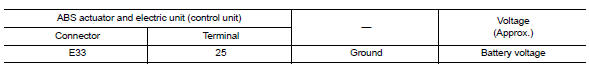
Is the inspection result normal? YES >> GO TO 3.
NO >> Repair or replace malfunctioning components.
3.Check abs actuator and electric unit (control unit) ground circuit
Check continuity between ABS actuator and electric unit (control unit) connector E33 terminals 13, 38 and ground.
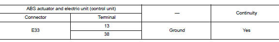
Is the inspection result normal? YES >> Replace ABS actuator and electric unit (control unit). Refer to BRC-110, "Removal and Installation".
NO >> Repair or replace malfunctioning components.
 C1130 Engine signal
DTC Logic
DTC DETECTION LOGIC
DTC
Display Item
Malfunction detected condition
Possible causes
C1130
ENGINE SIGNAL 1
When a malfunction is detected in ECM system.
...
 C1142 Press sensor
DTC Logic
DTC DETECTION LOGIC
DTC
Display Item
Malfunction detected condition
Possible causes
C1142
PRESS SEN CIRCUIT
When a malfunction is detected in master cylinde ...
Other materials:
Auto operation does not operate but manual operate normally (driver side)
Diagnosis Procedure
1.PERFORM INITIALIZATION PROCEDURE
Initialization procedure is executed and operation is confirmed.
Refer to PWC-29, "Work Procedure".
Is the inspection result normal?
YES >> INSPECTION END
NO >> GO TO 2.
2.CHECK ENCODER CIRCUIT
Check encoder cir ...
System description
DESCRIPTION
Engine Cooling System Schematic
CVT Models
Radiator
Water inlet
Reservoir tank
Thermostat
Engine oil cooler
Thermostat housing
Water pump
Cylinder head
Cylinder block
Water control valve
Water outlet
Heater
Electric throttle control actuator
CVT oil wa ...
Fog light switch (if so equipped)
To turn the fog lights on, turn the headlight switch
to the position, then turn the
fog light
switch to the position.
If the headlight switch is in the AUTO position
and the fog light switch is moved to the ON
position, both the fog lights and the headlights
(including all other ...
